Hello,
This is my first project built without a kit, and my fourth ever.
Here is the link: http://diyaudioprojects.com/Solid/ZCA/index.htm
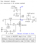
I'll attach the amp schematic on this post, and the power supply schematic on the next one. The above web site has been unavailable at times the last few days.
I would be grateful for any answers or advice.
--One resistance is shown as 15R/40W, could I use four 60 Ohm, 10W resistors connected in parallel here?
--Where the wattages of the resistors are not specified, does it matter, or would a half or quarter watt be ok?
--What voltage should the capacitors be, or does it not matter?
--How important is it to match the exact capacitance on the schematic, is it ok to go a little higher or lower?
--Is it ok to connect smaller caps in parallel to get larger cap values?
This is my first project built without a kit, and my fourth ever.
Here is the link: http://diyaudioprojects.com/Solid/ZCA/index.htm
I'll attach the amp schematic on this post, and the power supply schematic on the next one. The above web site has been unavailable at times the last few days.
I would be grateful for any answers or advice.
--One resistance is shown as 15R/40W, could I use four 60 Ohm, 10W resistors connected in parallel here?
--Where the wattages of the resistors are not specified, does it matter, or would a half or quarter watt be ok?
--What voltage should the capacitors be, or does it not matter?
--How important is it to match the exact capacitance on the schematic, is it ok to go a little higher or lower?
--Is it ok to connect smaller caps in parallel to get larger cap values?
Attachments
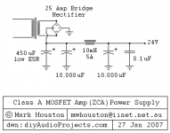
Here is the Power Supply schematic.
--Same questions about the caps, would it be ok for example to replace the low ESR 450uF cap with a low ESR 470uF?
--And do the cap voltages matter?
--What specs to I look for in a transformer for this power supply?
Thanks
--Same questions about the caps, would it be ok for example to replace the low ESR 450uF cap with a low ESR 470uF?
--And do the cap voltages matter?
--What specs to I look for in a transformer for this power supply?
Thanks
Attachments
hi Kinnja
before you decide on this design, are you aware this thing outputs somewhere between 5-10 watts of power? That means you need really efficent speakers to get the best out this amp.
good luck and hope it sounds good")
before you decide on this design, are you aware this thing outputs somewhere between 5-10 watts of power? That means you need really efficent speakers to get the best out this amp.
yes"--One resistance is shown as 15R/40W, could I use four 60 Ohm, 10W resistors connected in parallel here?"
The schematic says to use 0.5 watt reistors unless marked."--Where the wattages of the resistors are not specified, does it matter, or would a half or quarter watt be ok?"
The rails are 24 volts, so if you use 35V or more all should be well."--What voltage should the capacitors be, or does it not matter?"
yes can vary a bit and wont make much difference."--How important is it to match the exact capacitance on the schematic, is it ok to go a little higher or lower?"
yes"--Is it ok to connect smaller caps in parallel to get larger cap values?"
Typically you would use a transformer rated at minimum twice the power that a class A amp consumes, preferably 3 times. The author states the amp comsumes 60watts but i think its more like 40, so 120VA to 180va should work fine, even bigger is better."--What specs to I look for in a transformer for this power supply?"
good luck and hope it sounds good
Luke said:hi Kinnja
...before you decide on this design, are you aware this thing outputs somewhere between 5-10 watts of power?...
Typically you would use a transformer rated at minimum twice the power that a class A amp consumes, preferably 3 times. The author states the amp comsumes 60watts but i think its more like 40, so 120VA to 180va should work fine, even bigger is better....
Tom2 said:Kinnja,
I believe there is a mistake on the power amp schematic.
The polarity of 33uF tantalum cap is backwards.
The positive connection of the cap should connect to the 100k wiper.
You should email (Mark Houston) to confirm this.
Tom
Minion said:I think this amp actually only puts out 1w of power, at least that is what the Site says.....The Design is very simular to the Mosfet Headphone driver accept useing a Lateral Mosfet....
All the info is very much appreciated. I'll send him an email about that cap. Its ok if the amp does only put out 1W, I want to hear a Class A amp, and I would like some high efficiency speakers anyway.
Luke said:all that effort for 1 watt
One watt isn't much is it? The actual number should be around 5W. On the web page he says he burns up over 60W to get 5W Class A.
Tom2 said:Kinnja,
I believe there is a mistake on the power amp schematic.
The polarity of 33uF tantalum cap is backwards.
The positive connection of the cap should connect to the 100k wiper.
You should email (Mark Houston) to confirm this.
Tom
I sent an email, I haven't heard back from him yet but its only been a couple days.
I also noticed that the positive terminal of the speaker is connected to ground. If I build it as is, I guess I can get a cheap speaker, and stand clear of that cap when I plug it in. Hopefully only the cap would get fried. On the web site, he has an article by someone who built the amp, and he didn't say anything about any mistakes on the schematic though.
http://diyaudioprojects.com/Solid/Class-A-Mosfet/index.htm
Kinnja said:
I sent an email, I haven't heard back from him yet but its only been a couple days.
I also noticed that the positive terminal of the speaker is connected to ground. If I build it as is, I guess I can get a cheap speaker, and stand clear of that cap when I plug it in. Hopefully only the cap would get fried. On the web site, he has an article by someone who built the amp, and he didn't say anything about any mistakes on the schematic though.
http://diyaudioprojects.com/Solid/Class-A-Mosfet/index.htm
Hi Kinnja,
I got a revised drawing from Mark and I have updated the DIY Class A MOSFET amplifier webpage to reflect the change. The polarity was reversed. Mark also said in the end he went with a low ESR electrolytic, not tantalum. He also said the power is in the order of about 5W.
He cc'd me on his response to you. He later told me that your email bounced. Contact him again as it was a long message and I am sure he wants you to read it.
Cheers,
Gio
Hi Kinnja,
Have you considered building a Nelson Pass Zen amp? The design is well vetted and lots of people in the Pass forum have a lot of knowledge about building Zen's.
www.passdiy.com
The Zen 5 is pretty easy to make and within your power needs.
http://www.passdiy.com/pdf/zen-v5-lowres.pdf
Just a thought,
-David
Exactly what I thought when I saw the schematic. Just go take a look at the articles at www.passdiy.com and see if you don't find the documentation somewhat easier to understand.
Though the Zen 5 has nothing to do with the amp you were initially going to make, so take a look at Zen 1 instead. You can even get boards for the Zen 1 if you want.
Besides the fact that many of us knows the Zen amplifiers like the back of our own hands, so should you get into difficulties, the help and support is accurate and massive.
Magura
gmilitano said:
...your email bounced....
That is the second time recently I've been told that. I set up a new email account (different provider), I'll contact him through that one instead.
Thanks!
dw8083 said:
Wow, all the time I spend on the web, and I haven't seen that web site. I'm beginning to see some more projects in my future.
dw8083 said:Have you considered building a Nelson Pass Zen amp?
This amp is the basic SE Class A, very similar to the original Zen and Zen Lite. I think the only difference is the pot. The Zen Lite uses light bulbs instead of load resistors.
Kinnja said:That is the second time recently I've been told that. I set up a new email account (different provider), I'll contact him through that one instead.
I forwarded you the email this AM. It has not bounced back yet.
Regards,
Gio
This amp circuit looks interesting, but 2 things concern me...
first, it inverts the signal... I would use a transformer on the
front end and just connect it so that the input was inverted.
Second, those resistors are dissipating a lot of current...
maybe they should have their own heat sink!
first, it inverts the signal... I would use a transformer on the
front end and just connect it so that the input was inverted.
Second, those resistors are dissipating a lot of current...
maybe they should have their own heat sink!
For those interested, here is a link to another build of Mark's project.
http://members.optuszoo.com.au/m_edwards83/
and some high res photographs
http://diyaudioprojects.com/Gallery/displayimage.php?pos=-45
http://members.optuszoo.com.au/m_edwards83/
and some high res photographs
http://diyaudioprojects.com/Gallery/displayimage.php?pos=-45
zener_diode said:...Second, those resistors are dissipating a lot of current...
maybe they should have their own heat sink!
I didn't know there was such a thing, until I found some Aluminum Housed Resistors at mouser.com while I was ordering parts.
Today I finally made it to a stage of completion where I could listen to it. I connected it to some cheap speakers and a 20 Ohm stepped attenuator, it sounds good.
Thanks to all who have helped, and replied so far.
- Status
- This old topic is closed. If you want to reopen this topic, contact a moderator using the "Report Post" button.
- Home
- Amplifiers
- Solid State
- Class A Mosfet Amplifier and PS