ZCA - new build from Kinnja
Kinnja
You finally got to make a ZCA. Yours is now the forth in existence on this planet. Great to hear you like the initial sound. Like most electronic audio gear it will take a number of hours to settle in.
Gio thinks you may just have it at the bread board stage but we would dearly love to see your effort so far. You should have my e-mail. Please send me a few images.
The quality of the sound will benefit from a very solid case. I'm a believer of circuit resonance and go to great lengths to reduce this as much as I can. If you wants some extra ideas here let me know. My Synergy amp on Gio’s diyaudioprojects is my best effort so far at low resonance chassis etc.
Is there anything else I can help you with. Good work so far and drop me some photos.
Thanks mate.
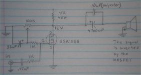
Air cooled resistros, upside down caps and signal inversion.
Kinnja
I forgot to answer some of the questions you asked earlier:
The resistive loading for the amp is via four 10W 15ohm resistors in series parallel to give me 15ohms. I fan them out on the cct. brd to allow an air between them. It appears to work OK. There is air hoes in the cct. brd below and the case has cooling holes top and bottom directly under and over the resistors.
The output cap looks reverse polarity but this is because the signal IS inverted through the amp. The suggestion is a tranni upfront to first invert the signal. I’m not sure I would bother.
The speaker is also reverse polarity again because the amp inverts. I have my speaker output wiring reversed in the amp. So you connect the speaker externally to the binding posts as normal. Pass does simular in his ZEN amps.
Hope this helps.
Re: ZCA - new build from Kinnja
No pictures yet, I don't have a digital camera.
The boards I used are the same kind you used on yours. Point to point, with most of the soldering underneath.
I got load resistors encased in their own aluminum heatsink that I thought were rated at 50W. After I got it all together I found that they were only rated 20W unless they were mounted on another heatsink, so I had to tear down and rearrange part of the amplifier board to make room for another heatsink. The load resistors are Arcol HS50 15R, I'm using one for each channel.
I used a 18V 250VA toroidal transformer, the power supply is putting out a little over 27V. So I adjusted the bias to 13.5V instead of 12V, let me know if that is wrong.
The case doesn't have any ventilation, but with the heatsinks, there is no room to put the lid on, and I wasn't planning on closing it up anyways. You were right when you said how hot the load resistors get, but they seem much cooler now that they have a heatsink.
Also like you said, the bass is much stronger than I expected.
Its connected to a passive line stage. The speakers I'm using now are old Sony 4-ways 89dB (1W, 1m). The volume is plenty for me in my small listening space.
I also have a grounded grid tube preamp that I haven't tried it with yet.
mhouston said:Kinnja
You finally got to make a ZCA. Yours is now the forth in existence on this planet. Great to hear you like the initial sound. Like most electronic audio gear it will take a number of hours to settle in.
Gio thinks you may just have it at the bread board stage but we would dearly love to see your effort so far. You should have my e-mail. Please send me a few images.
The quality of the sound will benefit from a very solid case. I'm a believer of circuit resonance and go to great lengths to reduce this as much as I can. If you wants some extra ideas here let me know. My Synergy amp on Gio’s diyaudioprojects is my best effort so far at low resonance chassis etc.
Is there anything else I can help you with. Good work so far and drop me some photos.
Thanks mate.
No pictures yet, I don't have a digital camera.
The boards I used are the same kind you used on yours. Point to point, with most of the soldering underneath.
I got load resistors encased in their own aluminum heatsink that I thought were rated at 50W. After I got it all together I found that they were only rated 20W unless they were mounted on another heatsink, so I had to tear down and rearrange part of the amplifier board to make room for another heatsink. The load resistors are Arcol HS50 15R, I'm using one for each channel.
I used a 18V 250VA toroidal transformer, the power supply is putting out a little over 27V. So I adjusted the bias to 13.5V instead of 12V, let me know if that is wrong.
The case doesn't have any ventilation, but with the heatsinks, there is no room to put the lid on, and I wasn't planning on closing it up anyways. You were right when you said how hot the load resistors get, but they seem much cooler now that they have a heatsink.
Also like you said, the bass is much stronger than I expected.
Its connected to a passive line stage. The speakers I'm using now are old Sony 4-ways 89dB (1W, 1m). The volume is plenty for me in my small listening space.
I also have a grounded grid tube preamp that I haven't tried it with yet.
Re: Re: ZCA - new build from Kinnja
That should not be a problem provided you are within the operating limits of the mosfet. The resistors will burn a little more power and you will get a little more power out of the amp.
What mosfet did you use?
Kinnja said:I used a 18V 250VA toroidal transformer, the power supply is putting out a little over 27V. So I adjusted the bias to 13.5V instead of 12V, let me know if that is wrong.
That should not be a problem provided you are within the operating limits of the mosfet. The resistors will burn a little more power and you will get a little more power out of the amp.
What mosfet did you use?
Re: Re: Re: ZCA - new build from Kinnja
There is no hum that I can hear on these speakers, but they aren't the most efficient.
Here is a link to the preamp, I think he sells a book on CD that has the schematic.
http://www.transcendentsound.com/preampkit.htm
I needed an excuse to get a camera, so I'll have a picture soon.
There is no hum that I can hear on these speakers, but they are not very efficient.
2SK1058 but I think it is made by Renesas now. I bought them on ebay.
mhouston said:Sounds like you have it all under control. Any hum?
Do you have a schematic for the valve preamp you talk of?
Borrow a digital camera, it will be for a good cause!
There is no hum that I can hear on these speakers, but they aren't the most efficient.
Here is a link to the preamp, I think he sells a book on CD that has the schematic.
http://www.transcendentsound.com/preampkit.htm
I needed an excuse to get a camera, so I'll have a picture soon.
There is no hum that I can hear on these speakers, but they are not very efficient.
gmilitano said:
That should not be a problem provided you are within the operating limits of the mosfet. The resistors will burn a little more power and you will get a little more power out of the amp.
What mosfet did you use?
2SK1058 but I think it is made by Renesas now. I bought them on ebay.
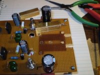
Kinnja said:This is only partially complete.
Nice clean layout. Be sure to post more photos when you are done.
Cheers,
Gio
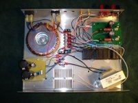
It is almost done. I was getting unhappy with the layout, and I decided that I might want to eventually put a cover on it. So I just about started completely over.
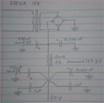
I removed the caps that were in front of the load resistor from the amp schematic, eliminated the extra 450uF and .1uF , and then drew them on the ps schematic. I still left it with two .1uF caps because the ps schematic already had one there, and I didn't want to change too much.
I also did the drawings with 470uF caps because that is what I was able to get.
Here is the amp.
Attachments
gmilitano said:What are you using as a preamp?
Right now, a passive line stage that I cobbled together. I'm using two 25K linear pots for volume, one for each channel. I can hardly tell from the sound that they are linear.
I also have a grounded grid preamp.
http://www.transcendentsound.com/preampkit.htm
I haven't hooked it up since I got this amp back together.
The passive line stage gives me the balance control I need, and I just plain like the sound--most of the time anyways.
satterfi said:Kinnja,
Would you send me a parts list ? I'd like to build one and it would save me hours of time searching Mouser or Digi-Key for the right parts.
satterfi
The only list I have is one I made when I was getting ready to start over. It all seems like pretty typical stuff, except for maybe the choke and the load resistors. I decided not to buy any new parts for the second build, but this is the list I was going to go by.
All the caps are 35V or more.
The load resistors are aluminum encased, you will need to read the data sheet to see their wattage without being mounted to a heat sink.
The heat sinks came out of a couple of old computers. The load resistors and MOS-FETs get *hot*. The bridge rectifier may need a heat sink too.
Make sure you understand about setting the bias.
Here is the list to make the amp according to the original schematic:
MOS-FET:
2SK1058 (ebay)
Choke:
Hammond 159ZJ
Transformer:
Avel Y236651 250VA 18V+18V Toroidal (Parts Express)
Caps:
3 X 140-ESRL50V470-RC 470uF (substitute for 450uF)
2 X 380LX103M063A042 10,000uF
1 X MKP1839410163 .1uF
2 X MKP1841447404 .47uF
2 X 140ESRL100V33-RC 33uF
2 X MKP1839410163 100nF(.1uF)
2 X DME1W10K-F 10uF
2 X UVR1H472MRD 4700uF
Resistors:
2 X CCF601M00FKE36 1M
2 X SFR25H0001001FR500 1K
2 X HS150 15RF 15R load resistors
Pots:
2 X MW22B-10-100K (100K, 10 turn pots)
Hum
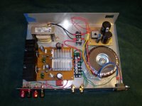
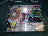
While I was tidying up the ground wires, it developed a bad hum. With the ground wires lengthened and pushed away from the transformer, the hum is barely audible. I can work on it some more, there is room for some "wire management", and I think I have some shielded cable laying around.
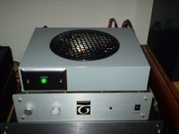
I would like it to look neater, but this is how it looks now for those few who might like to see it.
While I was tidying up the ground wires, it developed a bad hum. With the ground wires lengthened and pushed away from the transformer, the hum is barely audible. I can work on it some more, there is room for some "wire management", and I think I have some shielded cable laying around.
I would like it to look neater, but this is how it looks now for those few who might like to see it.
Attachments
- Status
- This old topic is closed. If you want to reopen this topic, contact a moderator using the "Report Post" button.
- Home
- Amplifiers
- Solid State
- Class A Mosfet Amplifier and PS