Its done. Thanks to all who helped.
Links to a couple pictures:
http://diyaudioprojects.com/Gallery/displayimage.php?pos=-81
http://diyaudioprojects.com/Gallery/displayimage.php?pos=-82
It sounded awesome. It had lots of detail, and good bass, but it did thump when I turned it on. It also had a little hum I could hear after my head-cold cleared up.
I since built a Capacitance Multiplier to replace the choke/pi filter in the PS.
The start up thump is completely gone, and I hear no hum at all when I listen for it. It sounded great with the choke, but to me, the cap multiplier is an improvement--even more detail and better bass.
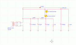
This is what I have so far. Its a variation of the one at
http://sound.westhost.com/project15.htm
Attachments
Hi John,
Nice work with the Capacitance Multiplier. Can you post a picture of your new power supply? Do the transistors in the Capacitance Multiplier need a heat sink?
Nice work with the Capacitance Multiplier. Can you post a picture of your new power supply? Do the transistors in the Capacitance Multiplier need a heat sink?
Kinnja said:
Links to a couple pictures:
http://diyaudioprojects.com/Gallery/displayimage.php?pos=-81
http://diyaudioprojects.com/Gallery/displayimage.php?pos=-82
It sounded awesome. It had lots of detail, and good bass, but it did thump when I turned it on. It also had a little hum I could hear after my head-cold cleared up.
I since built a Capacitance Multiplier to replace the choke/pi filter in the PS.
The start up thump is completely gone, and I hear no hum at all when I listen for it. It sounded great with the choke, but to me, the cap multiplier is an improvement--even more detail and better bass.
This is what I have so far. Its a variation of the one at
http://sound.westhost.com/project15.htm
gmilitano said:Hi John,
Nice work with the Capacitance Multiplier. Can you post a picture of your new power supply? Do the transistors in the Capacitance Multiplier need a heat sink?
The NTE392 gets a little hot, but I don't know if it really needs a heat sink. I did put heat sinks on both of the transistors anyway.
Hi, all.
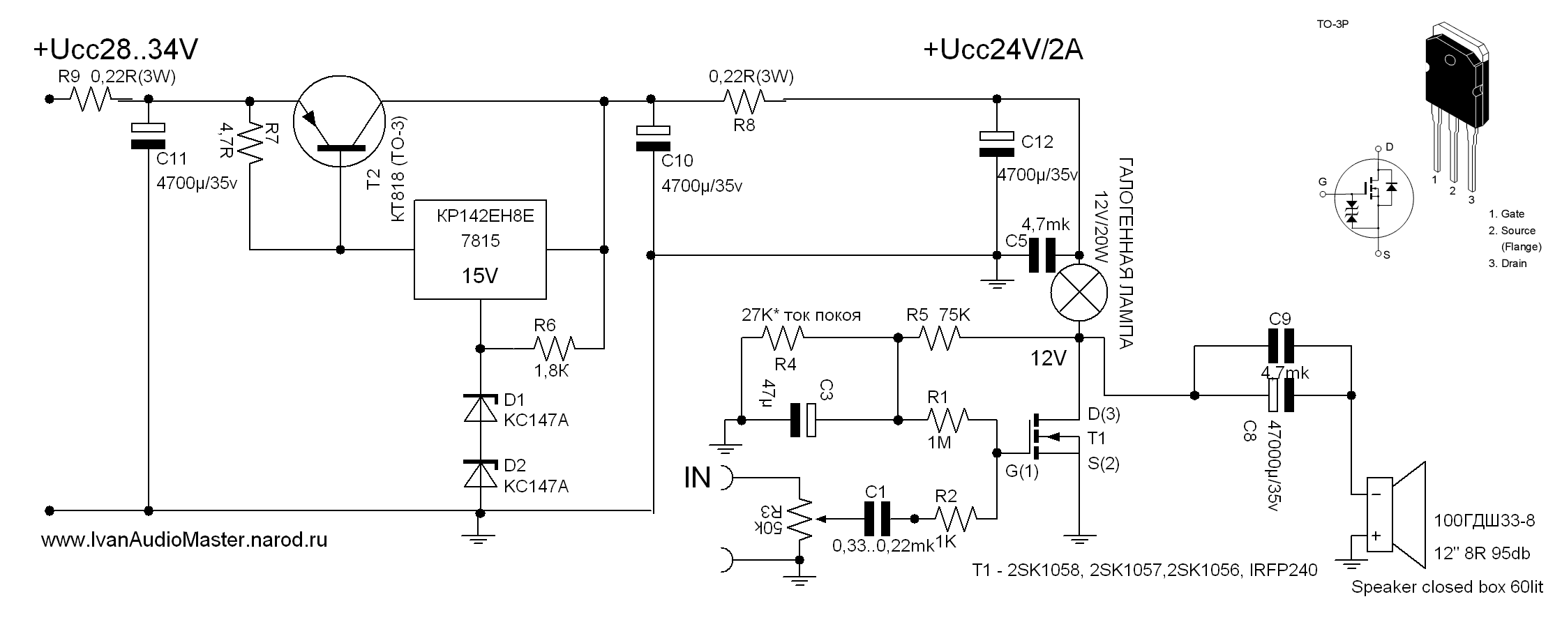
This is my realization ZCA.

And, photo
http://www.ivanaudiomaster.narod.ru/classAmyDEVICE.html

This is my realization ZCA.
And, photo
http://www.ivanaudiomaster.narod.ru/classAmyDEVICE.html

The sound very much is not bad.
I have dared to collect the finished amplifier.
This circuitry has very good results.
But low EFFICIENCY
It is necessary to reconcile only to the big radiators, transformers etc.
But expenses pay off with interest.
Now I work over the similar amplifier with throttle application.
It should increase EFFICIENCY.
http://www.vegalab.ru/forum/attachment.php?attachmentid=18829&d=1171806708
It is the scheme of my adherent. Konstantin Musatov's scheme. The throttle is supposed to be executed on the core 180va.
It is the scheme of my adherent. Konstantin Musatov's scheme. The throttle is supposed to be executed on the core 180va.
Thanks MHouston for creating and Kinnja for sharing this nice project 
Even Mr Pass thinks it's cool
Kinnja, it seems one of your colectors lacks a connection to power on your gyrator's diagram.
Two questions:
1) How many amps must the PS deliver?
I ask because I have used this regulator + gyrator called PowerReg:
http://www.pinkfishmedia.net/forum/showthread.php?t=39306&highlight=powerreg
It sounds very good on a LM3886 based amp...
2) What are the practical steps to set the bias?
I have some high efficiency front and back loaded horns that ask for nice low power amps contest
Thanks again,
M
Even Mr Pass thinks it's cool
Kinnja, it seems one of your colectors lacks a connection to power on your gyrator's diagram.
Two questions:
1) How many amps must the PS deliver?
I ask because I have used this regulator + gyrator called PowerReg:
http://www.pinkfishmedia.net/forum/showthread.php?t=39306&highlight=powerreg
It sounds very good on a LM3886 based amp...
2) What are the practical steps to set the bias?

I have some high efficiency front and back loaded horns that ask for nice low power amps contest
Thanks again,
M
maxlorenz said:Thanks MHouston for creating and Kinnja for sharing this nice project
Even Mr Pass thinks it's cool
Kinnja, it seems one of your colectors lacks a connection to power on your gyrator's diagram.
Two questions:
1) How many amps must the PS deliver?
I ask because I have used this regulator + gyrator called PowerReg:
http://www.pinkfishmedia.net/forum/showthread.php?t=39306&highlight=powerreg
It sounds very good on a LM3886 based amp...
2) What are the practical steps to set the bias?
I have some high efficiency front and back loaded horns that ask for nice low power amps contest
Thanks again,
M
I'm extremely pleased Mr. Pass even makes a comment on my seriously simple ZCA amp. Thank you Mr. Pass. It is partly because of some of his Zen amps I pursued the ZCA. There is many versions of the amp in many countries performing for its creators.
For biasing I used a couple of pots. The goal is to get halve the PS voltage across the FET and half across the load (naturally). I found in the first few days of play a lot of drifting occurs so continual tuning is required. Now after many months of play it is quite stable.
Take a good look at the article on http://www.diyaudioprojects.com/Solid/ZCA/ZCA.htm there is a lot of info there.
EWorkshop1708 said:Wonder how this Mosfet amp would sound with a heatsinked BiPolar transistor CCS (constant current source) instead of the 40W resistor?
Also, I'd like to build this, but with an E-MOSFET normally used for SMPS since they are tough.
This should increase efficiency. I wanted to keep it very simple.
Kinnja said:This is what it looks like at the moment.
I need to add a power switch, and do some finishing touches.
It sounds great.
Kinnja - Your work is excellent. I take it a personal compliment that you have built such a nice version of my ZCA amp. I still play mine regularly on my second system and still marvel at the transparency of its sound.
Board burnout
I know I'm a little late with a response to this posting but seeing the burn marks on the cct. brd prompted a remark. What I have fiound in the past works if you place a single medium thickness steel washer bewteen the resistors and the brd. under the mounting points, there is enough air flow resulting to stop any burning. It only takes a mm or two to make a whole lot of difference.
Only do this at the mounting points of the resistor. Possibly the coolest part of the heat sink.
Kinnja said:After I took it apart to start over, these were the burn marks left on the amp board from the two load resistors.
The load resistors are now mounted on the chassis with a heat sink.
I know I'm a little late with a response to this posting but seeing the burn marks on the cct. brd prompted a remark. What I have fiound in the past works if you place a single medium thickness steel washer bewteen the resistors and the brd. under the mounting points, there is enough air flow resulting to stop any burning. It only takes a mm or two to make a whole lot of difference.
Only do this at the mounting points of the resistor. Possibly the coolest part of the heat sink.
- Status
- This old topic is closed. If you want to reopen this topic, contact a moderator using the "Report Post" button.
- Home
- Amplifiers
- Solid State
- Class A Mosfet Amplifier and PS


