I have inherited a few bits and pieces from a power amp project that was never finished by someone else and I am in need of a power amp as mine has failed.
The only problem is that my understanding of electronics is minimal, though I try to learn... However, I can solder well, and sometimes even use a multimeter!
Is there anywhere I could find out how to successfully put them together with my limited skills/knowledge? Or if someone is willing to guide me though it....? And perhaps recommend a combination of components to select as I am sure I do not need to use them all.
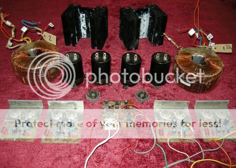
4 x Maplin GA28F amplifier boards 50w? 100w? MOS-FETS: K133's & J48's
2 x Antrim Transformers type YM48C, sec winding J2025. Some secondary windings have been removed. Transformer 1: 32.5v-0v-32.5v Transformer 2: 32.8v-0v-32.8v (original spec were Primary: 0-240V @ 50Hz Sec 1: 0-45V @ 6.94A rms/Sec 2: 0-45V @ 6.94A rms)
4 x ELNA Cerefine 63v 10,000uF Capacitors
2 x Bridge rectifiers
2 x Heatsinks
1 x Mapin GA17T 75w Bridging module (with anti-thump delay) - possibly faulty.
2 x pairs of 2SK135 & 2SJ50's
1 x Case
This is my system it will go with:
Pre Amps: Sound Audio VP-3a or Quad 33
Power Amp: Sound Audio HBP-60a - failed 🙁, or Quad 303 - buzzing in one channel 🙁
Integrated Amp: Leak Stereo 70
Speakers: Castle Acoustics 'Howard' original 70's model or Spirit Absolute 2
CD: Phillips CD104
Turntable: Garrard 301
Tonearm: SME 3009
Phono Stage: PS Audio PS IVA
Very grateful for any help.
The only problem is that my understanding of electronics is minimal, though I try to learn... However, I can solder well, and sometimes even use a multimeter!
Is there anywhere I could find out how to successfully put them together with my limited skills/knowledge? Or if someone is willing to guide me though it....? And perhaps recommend a combination of components to select as I am sure I do not need to use them all.
4 x Maplin GA28F amplifier boards 50w? 100w? MOS-FETS: K133's & J48's
2 x Antrim Transformers type YM48C, sec winding J2025. Some secondary windings have been removed. Transformer 1: 32.5v-0v-32.5v Transformer 2: 32.8v-0v-32.8v (original spec were Primary: 0-240V @ 50Hz Sec 1: 0-45V @ 6.94A rms/Sec 2: 0-45V @ 6.94A rms)
4 x ELNA Cerefine 63v 10,000uF Capacitors
2 x Bridge rectifiers
2 x Heatsinks
1 x Mapin GA17T 75w Bridging module (with anti-thump delay) - possibly faulty.
2 x pairs of 2SK135 & 2SJ50's
1 x Case
This is my system it will go with:
Pre Amps: Sound Audio VP-3a or Quad 33
Power Amp: Sound Audio HBP-60a - failed 🙁, or Quad 303 - buzzing in one channel 🙁
Integrated Amp: Leak Stereo 70
Speakers: Castle Acoustics 'Howard' original 70's model or Spirit Absolute 2
CD: Phillips CD104
Turntable: Garrard 301
Tonearm: SME 3009
Phono Stage: PS Audio PS IVA
Very grateful for any help.
Mind the white grease on the carpet 🙂 Sorry not quite what you wanted to hear. The amps are I believe from the 80's and based on Hitachi application notes, they are fine, not the ultimate in audio, but decent performers non the less. I would take these over the Quad's I think on balance.
It all comes down to how confident you are and whether you have the skills to put these in a case and wire up correctly, proper grounding etc. I would not bridge them, thats a sure way to ruin the sound, each module is good for around 100watts, more than enough for domestic use.
Were the modules kit built or complete. And wash those heatsinks in white spirit, that stuff gets everywhere.
Do you have the notes etc for the amps ?
Regards Karl
Hi,
the output FETs are rated @ 120Vds maximum.
This limits the supply rail voltage to an absolute max of +-60Vdc for the worst case conditions.
Use no more than +-50Vdc from normal mains supply.
I suspect these amps are designed to push 90W into 8ohm speakers.
I do not recommend 4ohm speakers nor 4 to 8ohm speakers for these amps.
I suggest you buy two 15mF/63V electrolytics for each amplifier.
AndrewT said:Hi,
the output FETs are rated @ 120Vds maximum.
This limits the supply rail voltage to an absolute max of +-60Vdc for the worst case conditions.
Use no more than +-50Vdc from normal mains supply.
I suspect these amps are designed to push 90W into 8ohm speakers.
I do not recommend 4ohm speakers nor 4 to 8ohm speakers for these amps.
I suggest you buy two 15mF/63V electrolytics for each amplifier.
Thanks Andrew - Do you think then that it is worth replacing the K133's & J48's with my 2 pairs of 2SK135 & 2SJ50's - I believe they are rated at maximum 160Vds - would this mean that I could get away with the 32.5-0-32.5v transformer I have...?
Also I would like to be able to drive 4ohm speakers and I am not in a financial position to buy new caps or tranformers...
If I have misunderstood your suggestions please let me know as my knowledge of these things is very minimal...🙄
transformers
Hi,
I think Andrew might have misread the voltage ratings of the transformers. The fact that someone has unwound some of the secondaries makes a huge difference here...you get more current, which is good and less voltage which is even better...you can always unwind more of the secondaries if you need to.
You should NOT use the bridging module if you want to drive 4 ohm speakers, the mosfets are close to their limits for normal operation at ~40v (45 sagging) rails, but will fail if asked to drive the same load bridged.
With the parts you have, I think you can build a very nice stereo ~75w, 8ohm amp. Simply use 2 of the amp modules, one of the transformers, a rectifier and a couple of the 10000uF caps.
You have enough parts to make 4 such channels. You could optionally use all the transformers and caps, to make the stereo amp, but the power supply rating would be far more than the capabilities of the output stage, perhaps making it pointless. If you wanted bulletproof amps, capable of maximal 4 ohm operation you could parallel the amp modules, at which point the extra power supply components would be more useful.
Depending on what your goals are you could easily sell the extra 'bits' to recoup costs of upgrading some of the other aspects of the amp, doubling up with more modern mosfets etc. AFAIK the more modern versions of the mosfets are no better sonically, but will be easier to obtain in multiples that can be matched.
HTH
Stuart
Mooly said:It all comes down to how confident you are and whether you have the skills to put these in a case and wire up correctly, proper grounding etc. I would not bridge them, thats a sure way to ruin the sound, each module is good for around 100watts, more than enough for domestic use.
Were the modules kit built or complete.
Do you have the notes etc for the amps ?
Thanks Karl for the white grease advice - my heatsinks are now gleaming like new! 😉
The modules I have were originally in kit form but seem to be put together well. And yes, I do have the notes that come with the modules - however, due to my lack of knowledge, much of it is not of any help. I struggle with little things like how to wire TWO modules to one power supply, whether or not the transformer goes to two rectifiers/sets of caps, or whether they both run off the same power supply etc etc...😕 The circuit diagrams don't allow for this, combined with my lack of basic knowledge. These are the notes: [/URL]MOS2
MOS4
However, I am very confident on the soldering and construction side of things, but which transformer wires to put where, that's another story..! Two of the four wires from the transformer have had their coloured insulation removed, which doesn't help!
I have found a similar project which may be useful but with little info:
Dave Goodman's MOSFET Amplifier
Re: transformers
Thank you Stuart for your clear helpful suggestions - ideally I would like to use 1 transformer, 1 or 2 rectifiers(i don't know anything about this side of things..?!), 2 or 4 caps(nor this..?!) with 2 amp modules.
However, I would like the amp to be able to cope with a 4ohm load - would that be possible without making things too difficult...? And if so, how might this be achieved..?
Stuart Easson said:
With the parts you have, I think you can build a very nice stereo ~75w, 8ohm amp. Simply use 2 of the amp modules, one of the transformers, a rectifier and a couple of the 10000uF caps.
You have enough parts to make 4 such channels. You could optionally use all the transformers and caps, to make the stereo amp, but the power supply rating would be far more than the capabilities of the output stage, perhaps making it pointless. If you wanted bulletproof amps, capable of maximal 4 ohm operation you could parallel the amp modules, at which point the extra power supply components would be more useful.
Thank you Stuart for your clear helpful suggestions - ideally I would like to use 1 transformer, 1 or 2 rectifiers(i don't know anything about this side of things..?!), 2 or 4 caps(nor this..?!) with 2 amp modules.
However, I would like the amp to be able to cope with a 4ohm load - would that be possible without making things too difficult...? And if so, how might this be achieved..?
transformers
Hi,
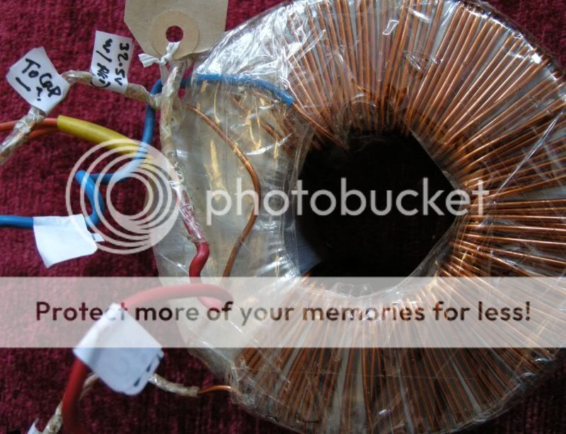
The secondaries on all the toroids I've played with have been on the outside of the core, from what I can see yours are the same.
If you post a closeup of the transformer I/we can probably guide you as to which wires are primary vs secondary, and then with a couple of simply measurements you can find which wire of which secondary to connect to the other secondary to make the 0v rail. After that you have two wires to connect to the recitifer from the transformer, two wires to run from the rectifier to the caps, then you have +/- 45v power ready to feed to the amps...
HTH
Stuart
Hi,
The secondaries on all the toroids I've played with have been on the outside of the core, from what I can see yours are the same.
If you post a closeup of the transformer I/we can probably guide you as to which wires are primary vs secondary, and then with a couple of simply measurements you can find which wire of which secondary to connect to the other secondary to make the 0v rail. After that you have two wires to connect to the recitifer from the transformer, two wires to run from the rectifier to the caps, then you have +/- 45v power ready to feed to the amps...
HTH
Stuart
Stuart,
I have downloaded Goodman's article.
The first two lines of the spec tell enough:
>75W into 4r0
>50W into 8r0
That is a good enough indicator that these amps are not designed to drive 4ohm speakers. They run out of current into low impedance loads.
Use them for 8ohm speakers only.
I have downloaded Goodman's article.
The first two lines of the spec tell enough:
>75W into 4r0
>50W into 8r0
That is a good enough indicator that these amps are not designed to drive 4ohm speakers. They run out of current into low impedance loads.
Use them for 8ohm speakers only.
4 ohm load
Running two modules from a single transformer, rectifier and caps will probably be fine for a benign 4ohm load.
If you really want to drive 'any' 4ohm load, paralleling the inputs and outputs (via 0.22ohm resistors) of a pair the amp modules will give you twice the current and power dissipation.
personally I'd build 'half' this configuration first, ie 1 transformer, rectifier, caps and two amps. Play with it for a while, when you are comfortable with the process, add in the second set of components and then parallel things to make the uber configuration.
Physically, do all the 'bits' you have fit in the case? Making a floor plan might allow you to decide if a dual mono construction with all the parts is possible. The rectifiers will need to be bolted to some metal surface, but the case may be more than adequate in the regard.
HTH
Stuart
There's a lot of sound advice hear, but I worry you have no practical experience, theres a lot of energy from those toroidal transformers and caps. You would have to do it bit by bit, use current limiting so nothing goes wrong if you make a mistake and test at each and every stage. Safety is important, fuses/grounding and the like. Not trying to put you off, if you really want to do this you will, just be aware of all it entails to reach the finished article.
Karl
Karl
Re: transformers
Stuart
This is the best pic I have at the moment - my camera is on loan...
I have established that the orange wires as primary. The labels you see on the wires are not to be relied upon...!
My own tests:
Between the RED and one of the unsheathed wires the voltage is 32.5Vac.
Between the other unsheathed and BLUE is 32.5Vac.
Can this tell us which wire is which?
Also, did you mean "+/- 65v power" in your last post?
The case I have is an old metal Maplin rack mount power amp case 18"x10"x5", but I would suggest it is only big enough for use with 1 transformer, two or 4 caps and 2 amp modules - anything more would be too tight and messy. The uber-amp must wait!
Stuart Easson said:.......and then with a couple of simply measurements you can find which wire of which secondary to connect to the other secondary to make the 0v rail......
......then you have +/- 45v power ready to feed to the amps...
Stuart
This is the best pic I have at the moment - my camera is on loan...
I have established that the orange wires as primary. The labels you see on the wires are not to be relied upon...!
My own tests:
Between the RED and one of the unsheathed wires the voltage is 32.5Vac.
Between the other unsheathed and BLUE is 32.5Vac.
Can this tell us which wire is which?
Also, did you mean "+/- 65v power" in your last post?
The case I have is an old metal Maplin rack mount power amp case 18"x10"x5", but I would suggest it is only big enough for use with 1 transformer, two or 4 caps and 2 amp modules - anything more would be too tight and messy. The uber-amp must wait!
Power...
Andrew is quite right, used individually these are 8ohm amps, in so much as the maximum continuous current the single pair of mosfets can sustain is ~7A each. This corresponds to the 4ohm peak power of 150w, 75w RMS. A lower impedance load will get less power and continuously driven would destroy the mosfets.
Adding the second module to the mix doubles the available current and thereby moves the critical limit from the output stage to the power supply. This is slightly wasteful in as much as you don't need an entire power amp to get the extra current capability, but since you have them...
I know from experience these amps are not delicate, but until the final configuration is achieved I'd keep them away from parties combined with 4 ohm speakers...
Stuart
Sorry, not read your post correctly, they are the primarys, the orange ones you refer to are they.
nice...
Mooly makes a good point, you can make the process much safer for yourself and the components by wiring a 40-60w light bulb in series with the primary, if there is a short it will glow brightly and limit power...
I've learned to ignore even my own labeling, unless I did it yesterday, so I understand your concern...
Since you already know which wires correspond to the primary, and secondary you have a simpler job...
Figuring out which of the secondary wires to use to form the 0v point...
For arguments sake I'd use the 'bare' wires as the starting point. With the other ends of the secondaries unconnected, connect the bare wires and measure the voltage between red and blue...ideally this will be 65v, indicating the bare wires are indeed the centre of the secondaries. If the voltage is ~0, you need to connect a bare wire to the opposite coloured one and measure the other pair. The pair that give you 65v will be routed to the AC terminals of the rectifier. The second link (MOS4) you provided shows the schematic for this set of connections.
Regarding the voltage the amps will end up running from: 31.5v AC secondaries will yield ~45v DC, after rectification and smoothing, hence your rails will be 45v at idle and will probably drop into the high 30's under full load.
Stuart
Pretty sure Stuart is right about the secondaries, the two bare wires will join together, this is the Zero volt point, DC as well as AC, and the red and blue will go across the bridge rectifier. What you have are two totally separate secondaries, you are after connecting them in series. It's so easy to visualise and so hard to explain.
Mooly said:.....theres a lot of energy from those toroidal transformers and caps. You would have to do it bit by bit......
Thanks for the advice Karl. As far as safety is concerned, I am aware there are 'hot bits' and that I must take it steady. My physical practical skills are definitely in good order, though very lacking electronically....
Forgot to mention, I also have two fuseholders...
😉
Mooly said:Is that 2 wires in the yellow sleeve ?
Yes Karl, There are two wires in the yellow sleeve, both are ORANGE and are the primaries.
Re: nice...
The third combination worked. I connected the blue wire to one of the bare ones and the voltage across the red wire and the other bare one was 65 volts.
OK... there was no reading between red and blue when the two bare wires were connected together. The next combination made the bulb light up... so no good(..?)Stuart Easson said:
Figuring out which of the secondary wires to use to form the 0v point...
The third combination worked. I connected the blue wire to one of the bare ones and the voltage across the red wire and the other bare one was 65 volts.
- Home
- Amplifiers
- Solid State
- Power Amp build bits - guidance required...