Bulb
Hi,
The bulb lighting corresponds to shorting the secondary, good job the bulb was in place, things get "exciting" when there are no limiters.
Now you've got the correct connections it's no big deal, doubtless you will have them labeled correctly, and you can begin to lay out the floor plan in your case. Once the physical layout is achieved, bolt everything down and wiring can begin...
There are a few points to consider in the process of building the amp. The transformers you have are large enough that I think you will need some other form of inrush current limiting or they will occasionally pop the fuse, the breaker or both. You are planning to have a mains fuse somewhere in there right ?...;-)
Another thing is to make sure the amp modules idle current adjustment starts at the lowest end of it's scale. I haven't read the article closely but I assume details are in the text somewhere.
Make sure the bolt through the transformer cannot touch the lid of the case. If it does, it creates a "shorted turn". Which is essentially an unintended secondary of 1 turn that is, as it's name suggests, shorted. As we've already seen shorted secondaries are bad...the light bulb lighting up will mostly indicate bad...brighter almost always meaning badder...
Good luck; "slow but steady" and "check everything in the light of a new day" are both sometimes worthwhile plans.
Keep the lightbulb in place until you are completely certain everything is working perfectly and has been for a day or two. You will be able to play the amp to pretty high levels with the bulb in place, in fact it should be a clear indication of output level...
Stuart
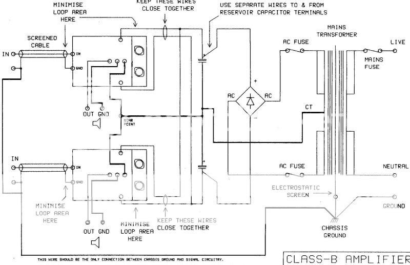
Might be worth adding a resistor, say 4700 ohm 1Watt across each cap while testing as once charged, you don't want to short them out accidently. You want an antisurge type fuse for the primary, once all O.K and the bulb comes out. You might get away with a 4 Amp, a 6.3 is probably better though. Keep the bulb in the primary side untill it's up, running and playing music. Check out www.cpc.co.uk for hardware, sockets etc. The input sockets must be electrically isolated from the case to avoid ground loops, so you want phono sockets with teflon/plastic isolators. Also it's the fashion to design so it looks "symmetrical", transformer in middle one amp each side. Personally I would not do this as the possibility for hum pickup caused by induced currents from the transformer, direct into the wiring is increased. Keep the tranny and caps over to one side of case and amps to the other, speaker sockets on one side probably the side near mains input and PSU and inputs at other farthest away from PSU.
Any mains switch has to be able to handle the inrush current, again cpc do some good ones, and they also do some mains filters which might be worthwhile. Don't forget wire, soft flexible is much nicer to work with in a few colours, and you need some screened cable.
Well it's a start 🙂
Any mains switch has to be able to handle the inrush current, again cpc do some good ones, and they also do some mains filters which might be worthwhile. Don't forget wire, soft flexible is much nicer to work with in a few colours, and you need some screened cable.
Well it's a start 🙂
Thanks to everyone providing such invaluable advice - a lot of my questions have been answered, many I haven't even thought to ask! I am taking it all on board and slowly digesting it, so please excuse me if my responses are somewhat delayed - plus I think my posts are still being moderated which delays them further.
Everything is making a lot more sense and today or tomorrow I will be visiting Maplin and a small independant components shop in Cambridge, for switches, phono & speaker socket etc.
My original layout was something like this Amp Layout 1 but will try some asymmetical layouts following Karls advice. The only problem with this is that the heatsinks next to each other are 1/2" too wide for the depth of the case... 🙁
Also, here are two missing pages from the amp module notes that I failed to post earlier MOS1 MOS3
Although a bit different I have some piccys on the "post your solid state pictures here" forum, post 283. How do you link to another thread ?, have to try and figure that out. This is an integrated design but may help with the layout.
Regards Karl
Regards Karl
The problem with the transformer in the middle is the potential for your wiring to pick up hum by the magnetic field from the transformer directly inducing a 50hz current into the wire. It's not insurmountable, but by keeping it in a corner as it were you avoid looping conductors around the transformer. You can also minimise stray pickup by actually rotating the transformer to hopefully find a null where it's influence is minimised.
I have just tried that but the transformer is actually even closer to (one of) the amp modules...
O.K. I think then keep it as your pic, but put both caps and bridge on say left and keep all your mains wiring to the right. Run all mains leads round edge of case to rear. I will sketch it out and see how it looks if you like. Whats it like if you rotate each amp 90 degrees with the amps facing to the rear. You would have to leave a gap 1cm or so between heatsink and case. I'll have a think 🙂
one thing...
...you might try is putting the heatsinks outside the case. This will have two obvious benefits, more room inside and better heat dissipation.
Unless the case is aluminium and the back panel very flat, it might be bad to simply bolt through the back panel, then you'd have to cut a couple of slots in the back panel. Of course if it is aluminum and flat, it would simply add more heatsinking to the mix, nearly always a good thing. Use white goop between layers, a lot will ooze out as things are snugged down. It's how I tell I'm done tightening, when no more oozes freely, it's tight enough.
For heatsinking I use anti-shake or split washers, it makes things less likely to come undone through being heat-cycled. After the first couple of heat-cycles (use a hairdryer if you can't play the thing loud enough to make it hot), re-tighten everything.
Happy building
Stuart
Mooly said:Whats it like if you rotate each amp 90 degrees with the amps facing to the rear.
Rotating the amps 90 degrees to face the back doesn't seem to be an improvement and could make access to the amp module a bit difficult - I think I will use the previous option...
Are you O.K. with the wiring and layout ? I would be tempted to get a 10k pot to use as volume and wire up and test each module I think first.
Re: one thing...
This is an option I have considered but due to the way the heatsinks wrap around the amp modules this does not create a lot more space - also, the back panel of my steel case already has many holes and cut-outs from someone's previous project - cutting such slots would make the back panel into a big mess...
Stuart Easson said:...you might try is putting the heatsinks outside the case. This will have two obvious benefits, more room inside and better heat dissipation.
This is an option I have considered but due to the way the heatsinks wrap around the amp modules this does not create a lot more space - also, the back panel of my steel case already has many holes and cut-outs from someone's previous project - cutting such slots would make the back panel into a big mess...
Is this going to replace your Quad, if so it's worth doing well. If you are like me you will not be happy unless it is. It may be worth a new case perhaps.
Mooly said:Are you O.K. with the wiring and layout ? I would be tempted to get a 10k pot to use as volume and wire up and test each module I think first.
I think I am ok on the layout, but am taking the rest very steady at the moment due to my lack of experience, and the little time I have on my hands. I have a lot to learn which means this is going to be a slow project. For example, at this moment I wouldn't really know where to wire in the 10k pot etc...

There's nothing quite like wiring it up (as a lash up) on the floor, and seeing how it performs. It's all very straight forward with modules like this. You want an old board to put it all on, and see if it all works as well as you hope. And, if it does you, will be much more motivated to complete the project.
Regards Karl
p.s. It's casework that I dislike most when designing and building projects, but it's surprising how good you can get finished projects to look, inside as well as out.
Regards Karl
p.s. It's casework that I dislike most when designing and building projects, but it's surprising how good you can get finished projects to look, inside as well as out.
Yes, when I do something, I like to make a good job of it. Case refinement and cosmetics are something I am ok with, but likely to come later on once I have got my head around the circuitry side of things - this is where I struggle..Mooly said:Is this going to replace your Quad, if so it's worth doing well. If you are like me you will not be happy unless it is. It may be worth a new case perhaps.
The amp may become a replacement for my Quad, or my other faulty amp but really it is something I would just like to achieve!
I will study that schematic you sent me, and perhaps try and draw something out for you guys to check for me - I expect that would be the safest way of going about this...
Some questions...
1. The antisurge fuses are in different positions on the two circuit diagrams - which do you recommend..?
2. I am unclear as to where the amp module for the second channel fits into the circuit on the first diagram - would it be best wired as in the second diagram..?
3 If I were to add a 10K pot (pots?) whilst testing, as suggested by Karl, where would this/these be connected..?
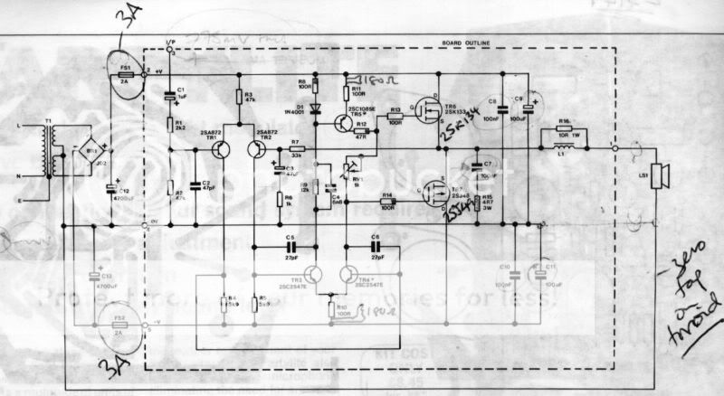
In the two diagrams below (the top one is that which came with my amp modules), could anyone please advise me the following:Mooly said:Are you O.K. with the wiring and layout ? I would be tempted to get a 10k pot to use as volume and wire up and test each module I think first.
1. The antisurge fuses are in different positions on the two circuit diagrams - which do you recommend..?
2. I am unclear as to where the amp module for the second channel fits into the circuit on the first diagram - would it be best wired as in the second diagram..?
3 If I were to add a 10K pot (pots?) whilst testing, as suggested by Karl, where would this/these be connected..?
Questions...
1) Either "place" is probably fine, but in the second case the fuses are protecting against a failure of the rectifier as well as the rest of the circuitry. More protection is probably better than less...but the answer to #2 adds an 'angle'...
2) Ideally each module will want it's own fuses, or a failure of one module can be a lot more spectacular. This means using more sets of fuses after the rectifiers and caps, since these are common to both channels. Neither schematic really shows this configuration, but the second diagram is closer, and all you need to do is insert fuses into the power lines as they head to each module. These can be larger fast-blo (~4A), since they don't have to cope with cap charging currents...
3) The 10k pot goes at the input to the amp module and essentially acts as a passive volume control to make sure you don't get any unexpected blasts. The input signal goes to the wiper, while the module connects to the top end of the pot. The other end is ground for input signal and module.
Hi,
is the signal ground at the input connected to either the speaker return or the line going to the star ground?
Is the star ground connected either directly or via a disconnecting network to the Safety Earth (chassis ground)?
F2.5A fuses between the smoothing caps and each supply line to each module will allow upto 100W into 8ohms without nuisance blowing.
Fuses before the smoothing caps will need to be considerably bigger, possibly >=T4A to prevent nuisance blowing.
- Home
- Amplifiers
- Solid State
- Power Amp build bits - guidance required...