AndrewT said:Hi,
is the signal ground at the input connected to either the speaker return or the line going to the star ground?
Is the star ground connected either directly or via a disconnecting network to the Safety Earth (chassis ground)?
F2.5A fuses between the smoothing caps and each supply line to each module will allow upto 100W into 8ohms without nuisance blowing.
Fuses before the smoothing caps will need to be considerably bigger, possibly >=T4A to prevent nuisance blowing.
Thanks Andrew for the fuse advice, but I don't know the answer to your questions - I would LIKE to know the answer to the questions..!
Fuses...
It should be easy enough to figure out what fusing arrangement you'd like. With PSU components that are common to both channels there are only a handful of options:
1) Fuse before the caps:
Fuse rating: slow-blo ~6A.
Con: Failure will be considerably more spectacular because much higher current can flow before the fuse pops.
Pro: Simple configuration, protects against failures of all components.
2) Fuse after caps, common:
Fuse rating: slow-blo ~4A.
Cons: Failure still allows more current than optimal. No protection for rectifier or cap failure.
Pros: Simple configuration
3) Fuse after caps, individual:
Fuse rating: fast-blo ~3A (Adjust to volume taste)
Cons: More components and wiring, no protection for power supply components.
Pros: The fuses are correctly sized to blow asap, but ideally no sooner.
AndrewT said:examine the PCBs or measure between the pins to find if these grounds are connected.
Andrew, I still can't get my head around that - perhaps you can see it in this pcb diagram or this circuit...
Hi,
What is not shown in the circuit/layout I sent is that the 2 amp modules themselves have rail fuses mounted on the PCB. It is important that there is no possibility of "nuisance" blowing of fuses as that in itself could cause a large DC offset to appear at the amp/speaker output if one only blew. Andrew and Stuart are both there or there abouts with their suggestions. F2.5 in EACH supply to EACH amp. A T6.3 for the secondary fuses feeding the rectifier and a T6.3 for the mains primary. T= anti surge type F = quick blow. The star ground is a single point that the earths are returned to. As I suspect you will not be making your own PCB's you need some means of connecting everything together here. Is the old style tag board still available I wonder. What I did not explain, that this layout shows is that the resistance of all wires is significant, hence the reason for a star ground technique. Due to large current pulses that flow between the smoothing caps, a volt drop occurs (AC Hum in other words ) in the wire joining them. If you were to tag earth wires here it would introduce hum into the audio. The star ground is a spur taken off this line , just as shown.
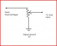
As to the 10K pot (any 10K 47K 100K will do) Stuart's description and Gains diagram I'm afraid are both incorrect (probably something in the water). It is the output signal that is taken from the wiper, the input from a C.D. is applied to the "top" and the "bottom" is earthed.
What is not shown in the circuit/layout I sent is that the 2 amp modules themselves have rail fuses mounted on the PCB. It is important that there is no possibility of "nuisance" blowing of fuses as that in itself could cause a large DC offset to appear at the amp/speaker output if one only blew. Andrew and Stuart are both there or there abouts with their suggestions. F2.5 in EACH supply to EACH amp. A T6.3 for the secondary fuses feeding the rectifier and a T6.3 for the mains primary. T= anti surge type F = quick blow. The star ground is a single point that the earths are returned to. As I suspect you will not be making your own PCB's you need some means of connecting everything together here. Is the old style tag board still available I wonder. What I did not explain, that this layout shows is that the resistance of all wires is significant, hence the reason for a star ground technique. Due to large current pulses that flow between the smoothing caps, a volt drop occurs (AC Hum in other words ) in the wire joining them. If you were to tag earth wires here it would introduce hum into the audio. The star ground is a spur taken off this line , just as shown.
As to the 10K pot (any 10K 47K 100K will do) Stuart's description and Gains diagram I'm afraid are both incorrect (probably something in the water). It is the output signal that is taken from the wiper, the input from a C.D. is applied to the "top" and the "bottom" is earthed.
Hope Gain does not mind, I've swapped his drawing round. If you want to run both amps up together you want a 10K Dual gang Pot, and for testing either linear or logarithmic law. As you hold the pot in front of you, shaft toward you, connections uppermost, the wiper (the one goes to your amp input) is the middle one. The left terminal is the input (from C.D.) and the right is ground. It's all dead easy, check the input to your amp on resistance on your meter and make sure the pot swings it from 0 ohms (a short) up to 10K or whatever value pot you chose. If you got Left/Right swapped it would work wrong way round, thats all.
I would try and get just one channel working first I think. Once it's working you can optimise the grounding, don't worry to much at this stage over this.
For safety a metal case has to be earthed. From here on it's not so easy, you can connect the Zero volt line to earth at ONE point only. It's whatever gives the lowest hum, and there are various tricks and techniques, again don't worry at this stage.
Are you intending trying a "lashup" by the way, just to see it all works, or are you going straight for the "build it in a case proper"")
I would try and get just one channel working first I think. Once it's working you can optimise the grounding, don't worry to much at this stage over this.
For safety a metal case has to be earthed. From here on it's not so easy, you can connect the Zero volt line to earth at ONE point only. It's whatever gives the lowest hum, and there are various tricks and techniques, again don't worry at this stage.
Are you intending trying a "lashup" by the way, just to see it all works, or are you going straight for the "build it in a case proper"
Attachments
Hi,
I should not have to examine your PCB from a picture when you have it to hand.
But, having checked the PCB pic, I can see that pin4 is the ground connection. It has the power decoupling and Zobel and low level stages and input all connected to it.
Pin4 is effectively the star ground. Unfortunately it is also a very dirty ground due to having both Zobel and decoupling attached to it.
If you connect the multichannel amplifier via the input RCAs you end up with a ground loop due to the on board star ground working against the off board star ground tying the two or more channels together.
AndrewT said:I should not have to examine your PCB from a picture when you have it to hand.
Sorry Andrew, it is not that I am unable to follow the lines on the PCB, it just the terminology used the I do not understand - I am very new to all this

Correct grounding, you could write a book on that one.AndrewT said:Hi,
If you connect the multichannel amplifier via the input RCAs you end up with a ground loop due to the on board star ground working against the off board star ground tying the two or more channels together.
Andrew, this is one of those things I can't reconcile in "my head"
As you say, when the input grounds are tied together, as they must be at some point, is when it all starts to fall to pieces. If you "fiddle" the issue by using say 10 ohm lift resistors this must also add distortion as the signal content changes. On Dougs layout the speaker negative being returned to a star point on the PCB makes this effect worse. I can't see any way round it ( not100%) . I did some research on this when I was designing my last amp, I actually built two small Op Amp "amplifiers using 4560's as these have a little more current capability than 4558 etc. What I did was to increase all "wiring" resistances to say 33 ohms and have say 600 ohm as the load. This really highlights the effect of tying the input grounds together.
ix66 If you are reading this, the message is unchanged
Get it wired up
Hi Ix,
you need to rationalise your grounds.
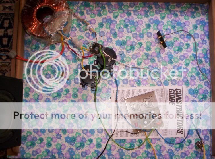
Star 1.) The input screen meets the pot common meets the blue ground wire.
Star 2.) The two blue grounds meet the PCB where the signal ground and power ground come out.
Star 3.) The blue ground meets the smoothing cap and the yellow from the terminal block.
Star 4.) The blue PCB ground meets the speaker return and meets the blue from the smoothing cap.
Star 5.) The centre tap meets the two yellow from the smoothing caps at the terminal block and meets the blue ground from the speaker return.
I hope I got that all right. The pic is off screen.
PSU star.) Keep one PSU zero volt for the centre tap and smoothing caps. Add one more wire from PSU star to Safety Earth.
Audio Star.) Keep one audio ground near the PCB.
Bring all the other grounding wires to this star, including one from the input RCA barrel.
I suggest you bolt these two stars using solder lugs so that you can experiment easily.
you need to rationalise your grounds.
Star 1.) The input screen meets the pot common meets the blue ground wire.
Star 2.) The two blue grounds meet the PCB where the signal ground and power ground come out.
Star 3.) The blue ground meets the smoothing cap and the yellow from the terminal block.
Star 4.) The blue PCB ground meets the speaker return and meets the blue from the smoothing cap.
Star 5.) The centre tap meets the two yellow from the smoothing caps at the terminal block and meets the blue ground from the speaker return.
I hope I got that all right. The pic is off screen.
PSU star.) Keep one PSU zero volt for the centre tap and smoothing caps. Add one more wire from PSU star to Safety Earth.
Audio Star.) Keep one audio ground near the PCB.
Bring all the other grounding wires to this star, including one from the input RCA barrel.
I suggest you bolt these two stars using solder lugs so that you can experiment easily.
congratulations on getting it working! i must have felt awesome the first time you powered it up and music came out ... nice work.
it would be a good idea to add two fuses, one in series between the bare copper secondary wire and the bridge rectifier, and the other in series between the red secondary wire and the bridge rectifier.
also consider soldering 4x 0.1 - 0.01uF ceremic caps across all 4 terminals of the bridge rectifier. this will help to reduce noise injection from the power supply.
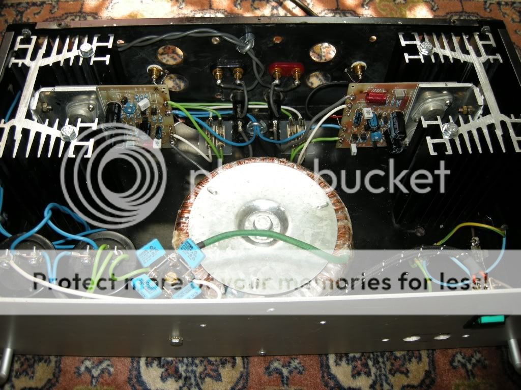
i would also bolt the unit to a proper heatsink before doing any 'serious' testing!
regards
it would be a good idea to add two fuses, one in series between the bare copper secondary wire and the bridge rectifier, and the other in series between the red secondary wire and the bridge rectifier.
also consider soldering 4x 0.1 - 0.01uF ceremic caps across all 4 terminals of the bridge rectifier. this will help to reduce noise injection from the power supply.
i would also bolt the unit to a proper heatsink before doing any 'serious' testing!
regards
gain said:congratulations on getting it working! i must have felt awesome the first time you powered it up and music came out ... nice work.
it would be a good idea to add two fuses, one in series between the bare copper secondary wire and the bridge rectifier, and the other in series between the red secondary wire and the bridge rectifier.
also consider soldering 4x 0.1 - 0.01uF ceremic caps across all 4 terminals of the bridge rectifier. this will help to reduce noise injection from the power supply.
Yes, it was great to hear music through it for the first time! The heatsinks are now on - thanks for the advice re fuses and ceramic caps.
Ian

- Status
- This old topic is closed. If you want to reopen this topic, contact a moderator using the "Report Post" button.
- Home
- Amplifiers
- Solid State
- Power Amp build bits - guidance required...