I have filled out the next line.
I see no way to save or register my entry.
Do I need to do anything else?
No Andrew, you are OK. Have just seen you there.
the FETs and BJTs do not need to be matched.I talked with UDailey about people who might want to have matched 2sk's and the extra 2sk's included.
All you need are two pair of B1 FETs (one pair/channel) that have similar Idss.
Well, I think we need to get this part sorted as to exactly what needs to be matched and to what tolerance because buying matched devices is pretty expensive and if it is in fact unnecessary then this becomes a much more affordable project and I think more people will do it.
So Andrew do you mean that the Mosfets or the Jfets must match and do all 4 need to match or do 2 match and 2 match?
Uriah
So Andrew do you mean that the Mosfets or the Jfets must match and do all 4 need to match or do 2 match and 2 match?
Uriah
Transformer is a Hammond 229D30. I got it from Mouser with the rest of the parts. Mouser number 546-229D30. Nice quality $23.57 30 V center tapped, 48 VA. Fits the bill nicely.
DC offset is 6.2 mv and 0.0 mv.😀 Can't do much better than 0.0.
The speakers are about 89 db efficient. The gainclone is one of Peter Daniels kits built as per his instructions.
About the pot, I am actually using a 50K noble I had kicking around. I think I am going to pick up one of those 20K stepped attenuators on ebay. Without building a lightspeed, I think that is the best long term option. Now I need to decide if this will be an integrated amp or pre amp/power amp seperates.
The B1 buffer has two jFETs, the 2sk170.
They run at roughly Idss.
Select the pair to have similar Idss and the lower run then biases the upper one.
That's all that is required.
Initially it was recommended that the slightly lower Idss jFET was used in the lower position and the higher placed in the upper position, but recently one of our Members reported good results with his system using the reverse assembly, i.e. using the higher Idss in the lower position.
I have not yet seen anyone else reporting similar results.
None of the other active devices in the regulator nor in the selector stages needs any form of matching nor precise selection.
The LEDs should be chosen to give the required PSU voltages, one regulator jFET MUST be a 2sk170bl, all the other regulator jFETs can be lower transconductance devices.
Last edited:
DaveM:
Hmm, 6.2mV...try another jfet couple on that side, it may go under 5mV.
I would get em out at a point, measure the 0mV side pair and try to get another similar couple to it. But after enough play, the 6.2mV side may go less. It does it some times.
Hmm, 6.2mV...try another jfet couple on that side, it may go under 5mV.
I would get em out at a point, measure the 0mV side pair and try to get another similar couple to it. But after enough play, the 6.2mV side may go less. It does it some times.
since the B1 buffer is included, the output cables can permit the selector/pre-amp to be separated from the power amp.Now I need to decide if this will be an integrated amp or pre amp/power amp separates.
The best place for the selector/attenuator is where the operator can easily reach it.
The best place for the power amp is right behind the speaker terminals.
It will be a very special operator that can reach behind the speaker to easily adjust volume/select an alternative source.
The B1 buffer has two jFETs, the 2sk170.
The run at roughly Idss.
Select the pair to have similar Idss and the lower run then biases the upper one.
That's all that is required.
Initially it was recommended that the slightly lower Idss jFET was used in the lower position and the higher placed in the upper position, but recently one of our Members reported good results with his system using the reverse assembly, i.e. using the higher Idss in the lower position.
I have not yet seen anyone else reporting similar results.
None of the other active devices in the regulator nor in the selector stages needs any form of matching nor precise selection.
The LEDs should be chosen to give the required PSU voltages, one regulator jFET MUST be a 2sk170bl, all the other regulator jFETs can be lower transconductance devices.
Awesome 🙂 Way better than having to match or buy a slew of Mosfets! That was going to bite the pocketbook. So what type of Idss precision should I look for? I am using the semiconductor analyzer from M3Electronics and it gives .01mA precision but I dont think I need that precision from what you are saying.
Uriah
Idss within 10% would work.
Within 5% will get closer to what Nelson Pass has recommended.
Within 2% is near perfection.
Within 1% is so tight, many of us cannot measure Idss to this accuracy AND hold all the other parameters at the correct values. I certainly can't. I doubt whether I can measure an absolute 5% tolerance for Idss.
Selecting 9mA+-0.3mA is probably good enough for the B1, but 8+-0.3 will work just as well and so will 10+-0.3
Last edited:
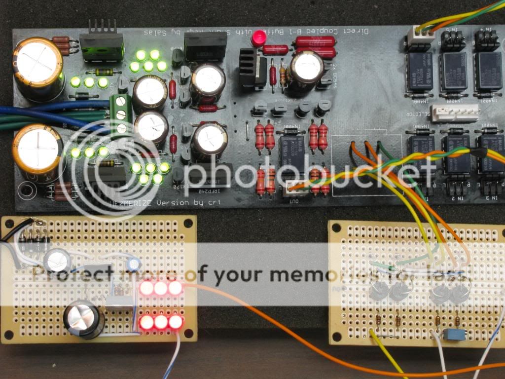
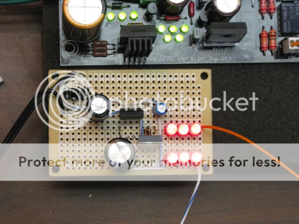
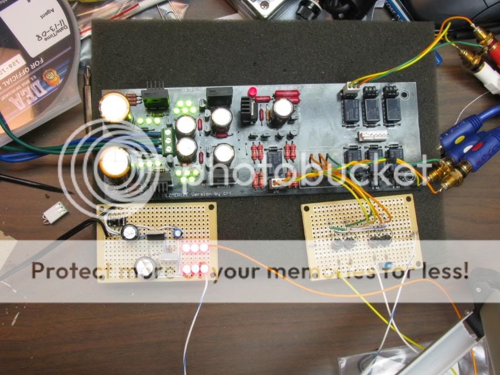
Pics as promised, please don't poke fun at my breadboarding efforts!
Possibly the most transparent B1 based assortment on the planet today.😉
looks like you have gr and not bl grade.Andrew, my batch of 2sk170 is coming in at about 5.45mA up to about 6.2mA. Bad?
Uriah
2.6mA Idss <= gr <=6.5mA Idss
6.0mA Idss <= bl <= 12mA Idss
Got them from Spencer. They have BL on the device. But these numbers are fine right?
Thanks for your patience Andrew.
Uriah
Thanks for your patience Andrew.
Uriah
Now I begin to wonder if your procedure has run into this problem?........... many of us cannot measure Idss to this accuracy AND hold all the other parameters at the correct values. I certainly can't. I doubt whether I can measure an absolute 5% tolerance for Idss...............
6mA? How does that compare to what Nelson Pass originally suggested. Did any of his later advice widen the acceptable range of device Idss?
my units from spencer run from 6.7ma to 10.5ma.
I used this method here than Woodturner Fran told me about.
http://www.diamondstar.de/transistor_matching_jfet.html
I use a HP Power supply as a source set to 9v.
I used this method here than Woodturner Fran told me about.
http://www.diamondstar.de/transistor_matching_jfet.html
I use a HP Power supply as a source set to 9v.
Last edited:
Nelson says BL and GR are fine for the B1 and later in the B1 thread says nothing is wrong with using V its just that he uses the previous two grades.
He says 5-10mA. I dont know if he ever revised that statement but the paper states 5-10mA.
That answers that.
The testing procedure I use is to stuff them all in a protoboard then let them sit for an hour and to get to room temp, not finger temp. Then I get out my Semiconductor Analyzer from http://www.m3electronix.com/sa.html and put a piece of wire on each probe and then stick the wires in the protoboard to access the device leads. Whamo, it takes a reading. It takes three different readings, one of them being Idss. I have tried leaving it on one device for a few hours and it in most cases it never changes from the original reading. It cycles through the three readings in about 10 seconds. I think it takes 3 readings per second.
Uriah
both Toshiba and Linear systems specify 10Vds for Idss specification.I use a HP Power supply as a source set to 9v.
One cannot expect the results to be correct when using the wrong voltage!
I got my SK17's from TECHDIY as a matched quad. They should be pretty close, but I have not measured them myself. I assumed that the matched devices belonged in the B1 stage of the board and not in the power supply. I will poke at it when I get back. How low should I expect to get the offset?
0-3 mV will be great, up to 5 mV will be very good. Not that 6.2 mV means trouble, but it does not point to good matching. You wait a little, because after it will reach some thermal plateau it can drop. Also, if you drop your +side reg by substituting two 0.2V lower leds than those you got in the IRFP9240 bank 5 led string, it can help. You may lose the fortunate 0.0mV offset of the other side, but they may average closer as channels. All this is aesthetics though, it amounts to a grand total practical nothing most of the time in such a circuit.  There is no voltage gain to match.
There is no voltage gain to match.- Home
- Group Buys
- GB for DC coupled B1 buffer with shunt PSUs