Uriah,
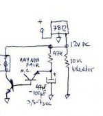
Thanks for your quick replythe yellow LED Vf is 1.8v to 2.5v, they can go to 5v for 2 in series as their maximum rating, my techer said LED is current source component that they actually not work in one Vf? I just increase the CCS current and they go to 5v, is that any problem if the CCS resistor is less than 22R, which is too much current to feed to the LSPD? or just not over 5v is OK? My current setting is 4.98v

They force feed nothing to the LSPD, no worries. The LSPD draws what it needs, the rest is shunted through them leds to ground. Hey, nobody here matched leds found with 2,5Vf with the battery method I suggested?
So, I finished building my Mesmerize board up last night. Everything went well. I have not put power to is yet as I finished up real late and want a set of fresh eyes to look everything over before I power it up.
Nitpicking comments about assembly... The holes for the 1/2 watt resistors were a bit small. The leads did go in, but they were a real PIA. LED orientation would be really nice to have marked on the board. About wiring the input selector switch. I haven't done that yet, and it is not clear how it should be done. It would be great to label + and - and input #
Otherwise it was a smooth build with no real significant issues. Nice work.
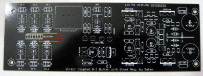
The right most pin on the selector connector is the ground, as you face the board, the last one towards the main circuits, near the word ''selector''. There goes the switching. All the other pins are for each position to select. Will ask Crt if he can do something about the labeling of the leds and the connector's header.
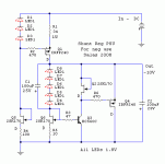
Attachments
This relay is pin compatible.
http://www.mouser.com/ProductDetail/Tyco-Electronics/D3009/?qs=HTr%2boA4jRinlxbjmWiwjSA==
Any reason to go with 5V vs 12V? Think we should just narrow it down to one choice.
IRT the LEDs I think orientation is always nice to have on the board.
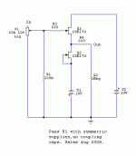
So we need to match 4 2SK170 and the Mosfets. Do the BC546 need to be matched? Should BC550 or BC560 compliment each other in any way or just stuff them in?
Lets say someone buys a few of these boards and sits on them for a few years and then cant find the BOM. That regulator not being labeled might be frustrating as well as the value of its cap.
The three holes in the center near the jumper could be labeled.
Uriah
http://www.mouser.com/ProductDetail/Tyco-Electronics/D3009/?qs=HTr%2boA4jRinlxbjmWiwjSA==
Any reason to go with 5V vs 12V? Think we should just narrow it down to one choice.
IRT the LEDs I think orientation is always nice to have on the board.
So we need to match 4 2SK170 and the Mosfets. Do the BC546 need to be matched? Should BC550 or BC560 compliment each other in any way or just stuff them in?
Lets say someone buys a few of these boards and sits on them for a few years and then cant find the BOM. That regulator not being labeled might be frustrating as well as the value of its cap.
The three holes in the center near the jumper could be labeled.
Uriah
They force feed nothing to the LSPD, no worries. The LSPD draws what it needs, the rest is shunted through them leds to ground. Hey, nobody here matched leds found with 2,5Vf with the battery method I suggested?
Thanks Sala, I just read the old post too, I think I was successed
 The sonic of LSPD really excellent I can't live without them now
Any reason to go with 5V vs 12V? Think we should just narrow it down to one choice.
IRT the LEDs I think orientation is always nice to have on the board.
So we need to match 4 2SK170 and the Mosfets. Do the BC546 need to be matched? Should BC550 or BC560 compliment each other in any way or just stuff them in?
Lets say someone buys a few of these boards and sits on them for a few years and then cant find the BOM. That regulator not being labeled might be frustrating as well as the value of its cap.
The three holes in the center near the jumper could be labeled.
Uriah
The reason is that 5V relays have been bought early from ebay by enough people, and its good to have 2 options, easier to hit some available deals. Its just a matter of using or not the Vdrop 300 or 600 resistors.
If you match everything, you are going to get nicely symmetrical voltage read outs, that mean nothing to the B1 performance. Some reg assymetry usually works towards lower DC offset in this case.
For the labeling suggestions I will email Crt, maybe he can enhance the labeling layer before final order. If he can't bother, I guess those things are a bit odd but not tragic. Has to have some degree of involvement, its DIY after all.
True, as you change current to LED the voltage drop changes. We would like to start with 5V. 4.98 really is nice and I wouldnt worry at that point. When you use the 100R resistors in front of the LDR then the current is not a worry and especially when you have a pot inbetween as well.
More Lightspeed questions should probably be in Lightspeed thread or power supply over in Salas power supply thread. All over the place
Uriah
Thanks for your help too, just stop the OT here
Thanks Sala, I just read the old post too, I think I was successed
No big deal, I just hope its really worth the effort over battery or LM317 voltage reg. If someone does a comparison, let us know in the LSPD thread. Its glowing nicely at least.
OT stop as you say. More on LSPD thread.
suggestions I will email Crt, maybe he can enhance the labeling layer before final order. If he can't bother, I guess those things are a bit odd but not tragic. Has to have some degree of involvement, its DIY after all.
Hey, if I got it to work with only a few questions and not blowing it up, that's not too hard.
I would agree the LED's were the part you had to think about, as your mounting and soldering, you wonder if you did it right. Some of us can put up some cut and paste pic's of assembly as well to help. I will see if the google doc space can do that, or at least a URL to the correct post.
As long as labeling changes, that's fine. But lets not get hyped up about structural changes please, as respining the board now in large order takes on significant risk I dont want to be part of. I think these little boards are of good quality.
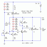
TEA-BAG
Extra's
I talked with UDailey about people who might want to have matched 2sk's and the extra 2sk's included. I realize that buying a bag of 100 or so for 8 of them may be an extra cost that can be avoided.
So I have added the column to the google document to indicate if one wants a set of 2sk170's (4 patched, 4 not) included with their board. It maybe possible to get some of his matched LDRs as well.
This of course is just an idea at this point, but would make a small mini kit a possibility. I could get these all shipped to me, then shipped with the boards.
If your interested in this idea, sign up on the current google Wiki.
Tea-Bag
Hey, if I got it to work with only a few questions and not blowing it up, that's not too hard.
I would agree the LED's were the part you had to think about, as your mounting and soldering, you wonder if you did it right. Some of us can put up some cut and paste pic's of assembly as well to help. I will see if the google doc space can do that, or at least a URL to the correct post.
As long as labeling changes, that's fine. But lets not get hyped up about structural changes please, as respining the board now in large order takes on significant risk I dont want to be part of. I think these little boards are of good quality.
TEA-BAG
We can do a simple construction help document to show how the LED ' are to be inserted correctly along with all additional instructions with the layout. I also thought about schematics that should go with this - it should be fine for constructors to follow. We do not need any change to the PCB as it is fairly complete with values / diode and transistor orientations.
decent numbers have signed up - encouraging numbers
GB is doing great
kannan
Mines been up for three days now, 8 hrs a day and really sounds great. I need to finish the Lightspeed though, been crazy busy these last few days. (and Salas I did not match a thing! I will do that when I have time, I am sure the baby shunt will be great. It has been going now all day and 5.00VDC, thanks)
I think that if we can consolidate all the disparate info in the thread into a document with the silkscreen, schematic and any gotchas we are good to go. I had a lot of fun building this, all I needed to do was be familiar with the thread and searched through it a time or two to find the answer IE: LED orientation.
I think that if we can consolidate all the disparate info in the thread into a document with the silkscreen, schematic and any gotchas we are good to go. I had a lot of fun building this, all I needed to do was be familiar with the thread and searched through it a time or two to find the answer IE: LED orientation.
Here are the elements again. When everybody is ready they can be nicely presented in a zip. Circuits, best BOM, construction pics. I have emailed crt about revising some labeling, if he comes up with a new labeling (especially for the leds orientation) I will let Tea-Bag have it.
Attachments
This of course is just an idea at this point, but would make a small mini kit a possibility. I could get these all shipped to me, then shipped with the boards.
That's a great idea! Signed up already.
I have thought about sending a heads up message to the members who ordered pcb's via the old wiki and who have lost sight of the project following the roadblock. Here is what I thought I might send them. We'll all end up getting a better price, if they jump on the bandwaggon again ... and there won't be a need for a second group buy a month after the first one.
What do you think of something like this:
"I am sending you this message because you had ordered pcb's for the "Direct Coupled B-1 Buffer with Shunt Regulator by Salas" before the design got hijacked.
The old orders live on in the old wiki, but they have become meaningless. You can take a look here:
http://www.diyaudio.com/oldwiki/index.php?page=GroupBuyDirectCoupledBOne
The old pricing is no longer valid and the design has actually been improved.
The Group Buy project has since recovered and a new pcb has been designed by Salas and crt. Tea-Bag has offered to manage the group buy. There are pictures of the boards as well as pictures of some of the prototype builds available in the group buy thread.
http://www.diyaudio.com/forums/showthread.php?t=147075&page=44
Orders for the new pcb's now use a google spreadsheet. Hypnotize is the Basic board with only a delay relay on output for avoiding DC offset hickups during on/off. It can be used as a one input buffer or else augmented with a classic input switch. Mezmerize is the evolution of the Deuxe B1 design. It uses the same shunt regulator and audio circuit as the Hypnotize board, but with 6 relay switched inputs. Pricing for the pcb's depends on volume and it has not been finalized, but it is likely that it will come in under USD 10.00.
The new group buy speadsheet lives here.
http://spreadsheets.google.com/ccc?key=0An3nVM43ZbQndHJSMVNSLVBwbVFUSEh5cXI3WnpDRnc&hl=en
This is just a heads up in case you are still interested in building this direct coupled version of the B-1 buffer."
I don't know, if that covers it. Feel free to comment and/or edit.
I have thought about sending a heads up message to the members who ordered pcb's via the old wiki and who have lost sight of the project following the roadblock. [/SIZE]
Nice idea - just to remind those will definitely bring back the interest and order.
I had increased my qty with the same idea of contributing more to DIYAudio donation/bring the PCB price ( i can always think of using the pcb).
kannan
- Home
- Group Buys
- GB for DC coupled B1 buffer with shunt PSUs