Doesn´t those relays have a standard pinout so that other brands can be used?
Yes - you can check the catalog - i think 0.1 inch (2.5mm) pitch for pins. Prefer using good brand like Omron /Panasonic will help for long term reliability
kannan
Yes,Omron I can get.🙂Prefer using good brand like Omron /Panasonic will help for long term reliability
Consider the Lightspeed a pot. If he is connecting it to where you would normally use a pot, I would consider it a pot.
Uriah
Uriah
Yes,Omron I can get.🙂
I am using omron - mentioned in the BOM - caused relay chatter - ofcourse cured by the cap on BC550 - beware when you use Omron - I also used 12 V relay as the power supply is 12 V / can avoid a series resistor if you use 12V
relay
kannan
But Tea-Bag uses Nais? If so, back to 1sq2.🙁 He hasn't put the power on led in yet though?. So to be exactly like the other two never chattering protos.
Consider the Lightspeed a pot. If he is connecting it to where you would normally use a pot, I would consider it a pot.
Uriah
Which is exactly my intention. I hope to complete it tomorrow. I could not wait to connect the DC-B1 this afternoon though and connected it with a USB DAC so I could use the PC to control volume.
BTW I am having a small issue with the baby shunt from Salas in the Lightspeed thread.
I can only get 4.5v out of it... Any ideas. Thanks
Remove an LED or change the value of the resistor. One of them is sure to change the voltage.
I have not used his regulator yet but a guy posted on Lightspeed thread of using it with success.
The LED you use makes a difference. If it drops to much voltage then thats what you get. Mess with it or just use the LM317 and then get the regulator working right and switch it back.
4.5V is to low. They will either turn right off or start going to high in resistance.
Uriah
Which is exactly my intention. I hope to complete it tomorrow. I could not wait to connect the DC-B1 this afternoon though and connected it with a USB DAC so I could use the PC to control volume.
BTW I am having a small issue with the baby shunt from Salas in the Lightspeed thread.
I can only get 4.5v out of it... Any ideas. Thanks
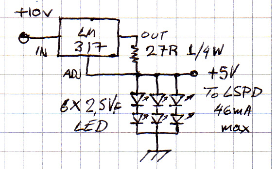
Use a 22R resistor first. You can use a 50R trimpot also so to nail it, but replace the final value with a standard resistor, bcs if a multiturn, has too tiny a wiper to survive the current reliably in the long term. Then if it does not come up to 5V, either see which led isn't matched, or lift the whole array with a diode between leds low line common and earth. Leave the 22R in anyway, gives more current to the leds so to reach Vf when LSPD is at its most consumprion.
But Tea-Bag uses Nais? If so, back to 1sq2.🙁 He hasn't put the power on led in yet though?. So to be exactly like the other two never chattering protos.
I just put an LED green, red amber. Without the cap on, noise still present.
I will try the BC550's from BillyK as last ditch effort.
I got my parts today. I've hit a bump in needing to match LED's. My cheap meter is not reading anything on the LED's in diode mode. Reads standard diodes fine, but LED... Nothing. I have a better meter at work I will try tomorrow. Hopefully I can have something up and running before the weekend.
I got my parts today. I've hit a bump in needing to match LED's. My cheap meter is not reading anything on the LED's in diode mode. Reads standard diodes fine, but LED... Nothing. I have a better meter at work I will try tomorrow. Hopefully I can have something up and running before the weekend.
Get a 9V battery and a 1k2 resistor. Use 3 crocodile clips. Connect from plus to resitor to led to minus. Measure the Vf on leds. Just put your meter in voltage mode across the lit led. Its more reliable because it measures at 6mA ballpark each one. Everybody gets a bit more than 10V regs bcs the DVMs that measure diode drop, measure at too low a current and the leds don't reach full Vf. No real problem if overshooting a little in the end, but the battery method is better for real Vf and match.
Which is exactly my intention. I hope to complete it tomorrow. I could not wait to connect the DC-B1 this afternoon though and connected it with a USB DAC so I could use the PC to control volume.
BTW I am having a small issue with the baby shunt from Salas in the Lightspeed thread.
I can only get 4.5v out of it... Any ideas. Thanks
Decrease the 27R, or simple make with a trimpot, 4.5V is not bad anyway🙄
if the Vf of the lowest reading LED is less than 2.5V then you cannot get 5V out of the Reg.
If you have two 2.25Vf LEDs in series then the max voltage will be 4.5V
If you have two 2.25Vf LEDs in series then the max voltage will be 4.5V
Its propable. As it is also propable that the leds they got don't reach 2.5Vf without a little bit more current. The best test and match method is with a battery and a resistor at about Iled nominal per string (Iccs/3) given the CCS target setting. Also a 22R would give more current reserve at max load, and is still tolerable at min. That was a ballpark idea, needs a little tuning on an actual LSPD with leds at hand. They can lift the whole array with a single diode to earth in the end if with not that strong Vf leds, with minimal noise extra as I have mentioned a couple of times, and avoid tedious additional led sourcing & measuring.
P.S. The 10V-12V input voltage should be provided by a 317 or 7812 reg for best overall rejection and not directly from rectification and cap. I have seen that fingerx has done the variable CCS trim set and prereg in his nice LSPD photo in its thread with yellow leds already.
P.S. The 10V-12V input voltage should be provided by a 317 or 7812 reg for best overall rejection and not directly from rectification and cap. I have seen that fingerx has done the variable CCS trim set and prereg in his nice LSPD photo in its thread with yellow leds already.
Decrease the 27R, or simple make with a trimpot, 4.5V is not bad anyway🙄
His intention is to use a Lightspeed attenuator. Thats 4 more LEDs. The voltage drop is to much with those 4 to use 4.5V. It must be 5V.
Uriah
Great! Thank everyone, I will fiddle about with all of these suggestions and let you know how it goes. Got a few busy days ahead of me so it will take a bit. Meanwhile I am enjoying the sound.
Tea-Bag, I just got back from the post office I sent a couple of those BC550b your way. Hope they help.
Tea-Bag, I just got back from the post office I sent a couple of those BC550b your way. Hope they help.
Been doing some matching of 25 green led´s,and they where where very tight,most of them where 1.99v so im going to end up with nearly 10volts,but guess thats not a problem?Everybody gets a bit more than 10V regs bcs the DVMs that measure diode drop, measure at too low a current and the leds don't reach full Vf.
1) Changing the resistor did the trick, I added another 27 and got 5.15 VDC so all I need do is dial it in and will be good to go, thanks again for all the great input.
2) I used my meter's diode checker and matched all 16 out of about 120 of them but am still at 10.94 and -10.54... Should I consider rematching a batch using the above mentioned resitor method? Also the 240 closest to the rear is quite hot (uncomfortable after 10 seconds) followed by the 9240 (uncomfortable after 18-20 seconds) in the rear. The others are just warm. The regulator also need a sink as its close to too hot to touch.
2) I used my meter's diode checker and matched all 16 out of about 120 of them but am still at 10.94 and -10.54... Should I consider rematching a batch using the above mentioned resitor method? Also the 240 closest to the rear is quite hot (uncomfortable after 10 seconds) followed by the 9240 (uncomfortable after 18-20 seconds) in the rear. The others are just warm. The regulator also need a sink as its close to too hot to touch.
1) Changing the resistor did the trick, I added another 27 and got 5.15 VDC so all I need do is dial it in and will be good to go, thanks again for all the great input.
2) I used my meter's diode checker and matched all 16 out of about 120 of them but am still at 10.94 and -10.54... Should I consider rematching a batch using the above mentioned resitor method? Also the 240 closest to the rear is quite hot (uncomfortable after 10 seconds) followed by the 9240 (uncomfortable after 18-20 seconds) in the rear. The others are just warm. The regulator also need a sink as its close to too hot to touch.
Everybody is getting similar 10.9V and -10.5V range ie one side is about 0.5 V higher than the other leg - it does not affect buffer offset. Also the Mosfet can be held for 5 seconds without pulling out- you do not need heatsink for functioning. However placing a heatsink does not do any harm either
It is good to go -
kannan
- Home
- Group Buys
- GB for DC coupled B1 buffer with shunt PSUs