i made a post a few pages back with a list of part numbers from RS componenents.
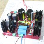
there is one mistake though. I used 4 x MUR diodes on my 6.3V rectifier , these dropped to much voltage and got very hot. So i changed them out for 6A 6a10 diodes which solved all my problems.
there is one mistake though. I used 4 x MUR diodes on my 6.3V rectifier , these dropped to much voltage and got very hot. So i changed them out for 6A 6a10 diodes which solved all my problems.
i made a post a few pages back with a list of part numbers from RS componenents.
there is one mistake though. I used 4 x MUR diodes on my 6.3V rectifier , these dropped to much voltage and got very hot. So i changed them out for 6A 6a10 diodes which solved all my problems.
Hi
have news of the outfit of your Pre?
Klaus
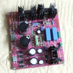
After i put a 120ohm resistor on the primary of my transformer to limit both my secondary voltages all heat sink temperatures are within 45 to 50C which is perfect.
I also changed the 4 6.3V heater diodes to standard 6 amp ones since the MUR 4 amp ones i selected did not work well at all.
The preamp is running perfect and all is well.
I have been using it MANY hours over the last few weeks and is very happy.
I am currently finalizing enclosure for this preamplifier and sending the drawings off to get aluminum punched and bend for the enclosure.
thanks quanghao
")
I also changed the 4 6.3V heater diodes to standard 6 amp ones since the MUR 4 amp ones i selected did not work well at all.
The preamp is running perfect and all is well.
I have been using it MANY hours over the last few weeks and is very happy.
I am currently finalizing enclosure for this preamplifier and sending the drawings off to get aluminum punched and bend for the enclosure.
thanks quanghao
In the process of putting my Parts list together for the Phono Stage, just want to clarify,Part C8,C16,C20,C28 are they .22uF or 2.2uF I am sourcing my parts from HiFi collective in Britain
Regards Jerry Kahmann
The caps out put, You can use from 0.22 uF to 2.2uF, Depend your Amplifier.
i have no clue really about tubes but if i understand correctly i understand their purpose thus:
1) they are directly in the signal path
2) they have to have higher voltage than 200 ( at least 250V)
3) they form a high pass filter
the size will have an effect on high pass cuttoff frequency. So if the cap value is too low you might loose low frequencies. if it is too high you start getting 5 and 10hz signals witch is in short a waste of power.
If i understand correctly , can someone help to explain which resistance is used to calculate high pass rc filter?
Or at least explain hoe to calculate cutoff frequency according to cap size.
thanks in advance
if i understand correct on the output you have 2 x 100K in parralel to give 50K.
So if you use 0.22uF with 50K you will get rc high pass filter with a -3db point at 14hz
Which is fine.
I think for the first two caps you will use the two 820k resistors in parallel? for this calculation.
long story short , it seems that even 0.22uF is more than enough to NOT "eat" into audible frequencies and still block dc.
old values ?
first interstage cap. 0.1uF (6.7Hz at -3dB) or 0.22uF (3Hz at -3dB)
RIAA
2 x 470K 1/4w 1%
2 x 47K 1/4w 1%
0.0135uF = 0.012uF + 0.0015uF = 12nF + 1.5nF silver mica
0.0046uF => 0.0047uF = 4.7nF silver mica
Rg = 2 x 1Mohm 1/4w 1% like original Phono 4
output cap 0.47uF (3.4Hz at -3dB) or 1.0uF (1.6Hz at -3dB) on 100K load (stepper attenuator)
change output resistor after cap to 2 x 1M
"first interstage cap. 0.1uF (6.7Hz at -3dB) or 0.22uF (3Hz at -3dB) instead of 2.2uF original"
what resistance did you use to calculate that?
"output cap 0.47uF (3.4Hz at -3dB) or 1.0uF (1.6Hz at -3dB) on 100K load (stepper attenuator) instead of 2.2uF original"
what resistor did you use to calculate that? does the 2 x 100K resistors on out not form part of this equation?
what resistance did you use to calculate that?
"output cap 0.47uF (3.4Hz at -3dB) or 1.0uF (1.6Hz at -3dB) on 100K load (stepper attenuator) instead of 2.2uF original"
what resistor did you use to calculate that? does the 2 x 100K resistors on out not form part of this equation?
- Home
- More Vendors...
- Quanghao Audio Design
- OLD THREAD Hi-end phono preamplifier by Andrea Ciuffoli