Listening ofthis NoGNFB integrated amp with germanium transistor output has confirmed an idea that Ge transistors are obviously superior to other types of transistors at the output of NoGNFB designs. Output impedance with one transistor (without paralleling) came about 0.08 ohms. Bandwidth is greater than 1 MHz. Even in comparison with the well-sounding bass from good GNFB amps, I have distinguished some new tiny bass details. Interestingly, the h21 vs Ic curve for 1T910A Ge transistor shows only growing behavior even in the range of collector currents 10 ... 20A.
The quiescent current of 1.25 A was chosen, since I was afraid of burning out the Ge.
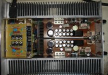
But, the main heat sinks are only a bit warm, I guess the idling current can be increased up to 2A.
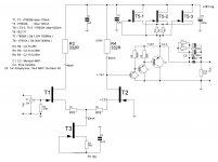
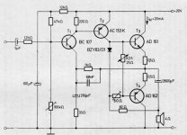
Voltage gain of the input differential stage, for the Idss of KP903 and resistor values indicated, is near 6.5. It is quite enough for me, usually I listen with the voltage gain range 2 ... 5.
Power supply is built with two R-Core transformers, every has 24V-3A and 10V-1A windings. Output voltages are further smoothed by "cap multipliers". Power supply socket is placed at the side panel, in order to avoid the neighborhood of power and input wiring.
The whole schematics is assembled point-to-point. The input pot is DACT 20 k.
Overall, the sound is excellent. As if the high-quality tube SE amp has been magically added by bass, and this is the bass that creates a new reference for me.
The quiescent current of 1.25 A was chosen, since I was afraid of burning out the Ge.
But, the main heat sinks are only a bit warm, I guess the idling current can be increased up to 2A.
Voltage gain of the input differential stage, for the Idss of KP903 and resistor values indicated, is near 6.5. It is quite enough for me, usually I listen with the voltage gain range 2 ... 5.
Power supply is built with two R-Core transformers, every has 24V-3A and 10V-1A windings. Output voltages are further smoothed by "cap multipliers". Power supply socket is placed at the side panel, in order to avoid the neighborhood of power and input wiring.
The whole schematics is assembled point-to-point. The input pot is DACT 20 k.
Overall, the sound is excellent. As if the high-quality tube SE amp has been magically added by bass, and this is the bass that creates a new reference for me.
Attachments
Interesting although I'm not familiar with the device/s you mention.
My first ever amp used Ge outputs (AD149).
I would not use Ge transistors, if they are slow, and if schematics would suffer from their thermal instability. These drawbacks are not relevant to the present schematics.
Also, I guess, the base region resistance of 1T910A is unusually small, since I have got output impedance modulus around 80 mOhms. Passband -1dB is more than 1MHz.
Not bad for simplest No GNFB schematics.
If somebody mentioned difference in bass between lateral MOSFETs and BJTs at output, that one could guess further improvement with Ge compared to Si BJTs.
Not bad for simplest No GNFB schematics.
Indeed
") It's not bad at all, and your quoted output impedance seems very good.
It's not bad at all, and your quoted output impedance seems very good. It is a really nice design... well done
A very long time ago... was a Brazilian kit made by Philips/Miniwatt factory.
regards,
Carlos
Hello, Carlos
Please, pay attention to the differences between that kit and this schematics.
Some of them, are:
1) this thread schematics does not experience power supply current modulation under signal conditions, PS does not stand in the signal path
2) it has No GNFB (Ge output transistors are not good for GNFB schematics, they are relatively slow)
3) it has No input cap
4) output cap is made with all possible care
5) passbands of the two designs I guess differ drastically
As for sound estimates, I have very good tube 300B SE amp, and it gives very good reference for mids and highs quality, I can easily estimate sound differences between traditional GNFB schematics and special schematics, designed for extreme high quality.
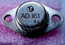
Comparing the 1T910A power Ge transistor (p-n-p) with AD162 (p-n-p) we can see:
AD162 Transistor Datasheet. Parameters and Characteristics.
Material of transistor: Ge
Polarity: pnp
Maximum collector power dissipation (Pc): 6W (35W for 1T910A)
Maximum collector-base voltage (Ucb): 32V (33V for 1T910A)
Maximum collector-emitter voltage (Uce): 20V (32V for 1T910A)
Maximum emitter-base voltage (Ueb): 10V
Maximum collector current (Ic max): 1A (10A average current for 1T910A, 20A pulse current)
Maximum junction temperature (Tj): 80°C (358K = 85C for 1T910A)
Transition frequency (ft): 1MHz (30MHz for 1T910A)
Collector capacitance (Cc), Pf: 150
Forward current transfer ratio (hFE), min/max: 50MIN (100...250 for 1T910A)
Manufacturer of AD162 transistor: PHILIPS
Package of AD162 transistor: TO37
Application: Medium Power, General Purpose
I guess, intrinsic resistance of the base region of 1T910A is some orders of magnitude less than that of AD162.
1T910A is really a peak of Ge technology. The output impedance 0,08 Ohms with 1T910A is not emulated by GNFB, it comes from intrinsic properties of the transistor, connected as emitter follower.
Last edited:
I built versions of both amplifiers: shown by DestroyerX with profound changes (my first version at 1998!, last in 2014), and one the like VladimirK (in 2014), but with valves in gain stage, AC coupled and using GT806B (with 16V/1.5A) in instead of 1T910. I tested versions with AC188 / IRF9160 / 2SB324 and 2SK77 to form the "Darlington" with good results even with AC188. 55. Damping factor using the IRF9610 "driver" = 55, and that including the output capacitor! Not bad for a amp operating in open loop! The distortion is the same at 1kHz or 20kHz (with all tr but the 2SB324), about 0.05% to 1W / 8R only 2H and 3H (with IRF9610). It sounds great, with an very open sound, in loudspeakers that require high damping factor.
The amplifier with AD161/162 I used only Ge transistors: 2SB486 PNP low noise at the input, 2SD352 in VAS (ground referenced and not supply referenced = far more better PSRR) and AD161/162 at the output with quiescent current of 200mA, and 20V supply. The thermal compensator is an AC188. As in this amplifier transistors used are all low fT, the distortion increases as going up to 20 kHz starting from 1kHz. 1W / 8R (2H and 3H, with some 4H and 5H), we 0.03% THD at 1kHz and 20kHz to about 1% (but these amp is very stable due to "marriage" fT). The damping factor I do not measure. But I reduced him to the technique of defining the impedance of the amplifier, because with raw operation sound are harsh.
But I are an tube man and all of this serves to "non-typical" days...
1T910 is an ex-USSR part that is FAR advanced over any vintage Ge transistor you may find, unless you have access to really exotic military stuff (because orifinally 1T910 WAS really exotic military stuff). Developement of Ge technology continued behind the iron curtain long after it stopped in Europe and USA.
I like the design but have my misgivings about using KP903 as simple current sources, these parts really deserve a better use, I doubt there would be any serious degradation using a regular SI - or for that matter Ge - transistor as a current source. Especially for T3. Also giving each of the 3 parallel KP903 in the current source their own Rs would probably result in better current sharing.
I like the design but have my misgivings about using KP903 as simple current sources, these parts really deserve a better use, I doubt there would be any serious degradation using a regular SI - or for that matter Ge - transistor as a current source. Especially for T3. Also giving each of the 3 parallel KP903 in the current source their own Rs would probably result in better current sharing.
Excellent Ge transistors
Really, they are far more advanced than ordinary vintage Ge. I sawed the top of one damaged GT806B (my fault)(in time: ГТ806Б), and the die of the same does not resemble even remotely the vintage Ge (I need to take an photo and post here). The GT806B are not so advanced as the 1T910, but still belong to this class because they have excellent but not so good beta than 1T910, only a little loss to 10A (try it with almost any 10A Si transistor), have an 10MHz fT and provided the results I described in my previous post (the valve-IRF9610-GT806B, not the AD couter-example), and I confirm the impossibility of obtaining this performance with ordinary Ge (I tried the follower with AD149, the damping factor deteriorates, and 20kHz THD sucks).
For more info, I used Si MOSFET, the IRFP9240 (well, I don't know if Ge MOS exists...) on my current sources, with expected good results. Better for saving the rare high-fT Ge....
I used a CPU heatsink to keep GT806B in a good temperature even abusing the limits of the datasheet . They are robust.
Really, they are far more advanced than ordinary vintage Ge. I sawed the top of one damaged GT806B (my fault)(in time: ГТ806Б), and the die of the same does not resemble even remotely the vintage Ge (I need to take an photo and post here). The GT806B are not so advanced as the 1T910, but still belong to this class because they have excellent but not so good beta than 1T910, only a little loss to 10A (try it with almost any 10A Si transistor), have an 10MHz fT and provided the results I described in my previous post (the valve-IRF9610-GT806B, not the AD couter-example), and I confirm the impossibility of obtaining this performance with ordinary Ge (I tried the follower with AD149, the damping factor deteriorates, and 20kHz THD sucks).
For more info, I used Si MOSFET, the IRFP9240 (well, I don't know if Ge MOS exists...
) on my current sources, with expected good results. Better for saving the rare high-fT Ge....I used a CPU heatsink to keep GT806B in a good temperature even abusing the limits of the datasheet
. They are robust.Hello, DIYBras. In my case, I am drifting from SS to tubes, GM70 SE (with regulated 1200V B+, and 40cm2 output trafos, for better bass performance) is in use now (and PP with Toshiba 6GB8 is close to completion). But, the latest project, is a hybrid (tube two-stage driver with phase inverting 6:1 output trafo, followed by bridged transistor buffer stage, similar to that from this thread, but far more powerful, with radio-frequency 350W KT947A transistors at output).But I are an tube man and all of this serves to "non-typical" days...
Howerver, for tube guys who use 3-8W amps, the Ge based output stage is the best, I believe.
Last edited:
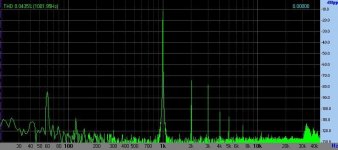
Some test results...
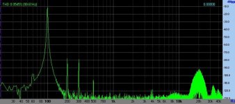
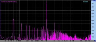
Here are some FFT test results from "conventional Ge"
The bump at 20kHz is due my test disc (not oscillations or suchlike). At time I executed this measurements, the internal sine generator from FFT program (VA) are polluting low level with high order distorition, and this test CD has pure sine signal.
Attachments
Last edited:
Some test results...
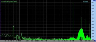
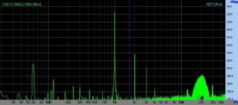
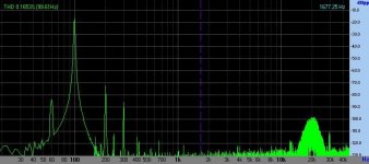
Now from russian Ge (excuse the line interference in some measurements)
V-MOS are from IRF9610 + GT806B
other are from AC188+GT806B (some AC188 selected for less THD20k)
Now from russian Ge (excuse the line interference in some measurements)
V-MOS are from IRF9610 + GT806B
other are from AC188+GT806B (some AC188 selected for less THD20k)
Attachments

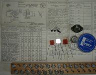
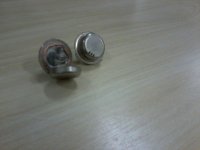
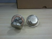
Russian Ge photo...
My cellphone camera SUCKS

Interesting round disc die and multi base-emmiter connections
These russian Ge sounds good for low power and closed sounding speakers (they became alive) not unlike my 300B amp, but with some differences due to enormous natural DF (damping factor) and others things
Wow, with such huge trafos in your ГМ70 amp the bass sure will sounds better than most commercial valve amps, due freedom from magnet nonlinearities...
My new "official toy"
http://www.diyaudio.com/forums/tubes-valves/240611-final-amp-2.html#post4353706 see photos at my last post
My cellphone camera SUCKS
Interesting round disc die and multi base-emmiter connections
These russian Ge sounds good for low power and closed sounding speakers (they became alive)
not unlike my 300B amp, but with some differences due to enormous natural DF (damping factor) and others thingsWow, with such huge trafos in your ГМ70 amp the bass sure will sounds better than most commercial valve amps, due freedom from magnet nonlinearities...
My new "official toy"
http://www.diyaudio.com/forums/tubes-valves/240611-final-amp-2.html#post4353706 see photos at my last post
Attachments
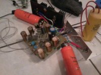
Last picture...
This is from my AD161/162 prototype ("conventional Ge"). Note different heatsinks for channels, because I used things at hand...
First time I built it was in 1996, in mono, using Telefunken output transistors and with more than ten times the actual THD (I upgrade the circuit several times since I start to using FFT analysis).
Attachments
Struth,
The PS don't stand in the OUTPUT signal path for in VladmirK thread project and also in mine Russian Ge, because both are SE with "original" output capacitor connection, like SE Power Follower from Andrea Ciufolli.Loudspeaker current goes isolated from supply because T5-1-2-3 are power JFET (pentode-like), configured as an current source (VladmirK, please correct me if I made some mistake about this part). Hence, current variations do not circulates in power supply. All loudspeakers current circulates between T6/T7/T8, ground and output capacitors. Some little pre current goes to R4 and circulates in power supply. My version is hybrid and not have "an R4" (hence zero power supply modulation).
(but PSU yes are in signal path for the conventional Ge: it are an trivial SEPP; the AD161 pull current from supply).
All normal PP versions I know have an node or two circulating current to PSU electrolitics (even the so-called "magic" Ciclotron...). BUT if you make some BTL PP ("dual SEPP balanced"), in class A you can average the sypply current variations to zero, like trafo coupled PP.
- Status
- This old topic is closed. If you want to reopen this topic, contact a moderator using the "Report Post" button.
- Home
- Amplifiers
- Solid State
- NoGNFB integrated amp with Ge transistors at output