Bay Area Tube Festival
Please see "differential (forced balance)" and "differential parallel feed" figures for examples of PP where for AC signals the power supply does not exist! One need to not forget the current sources and chokes concepts in order to analyze that circuits. Then, in pure class A average current tends to zero (but not zero with real devices, see again the paper: is averaged between the devices, NOT supply), making possible such circuits (and I verified that in reality). Because the choke or current source presence, output current is limited to 2x quiescent for delivering power to the load, i.e this circuits don't work in class B. In another words, the AC current/power circulates between load and two tubes (or transistors), and current becomes from supply ONLY at DC.
Of course for DC ALL circuits without exception uses electrons who circulates form supply.
Another AC/DC signal flow material: Active loads and signal current control
DIYBras, you are correct. But the matter is not in who correct - who wrong, matter is in big differences, how traditional emitter follower sounds like (signal (AC) current goes through-from PS rails), and how Ciuffolli-like follower (this thread) sounds like. Please, check the difference youself. Output cap must be from many small good quality electrolytics with decent shunts. Please, do not take 4700uF for output cap, like Andrea originally did. Passband estimates for 8 Ohms load has nothing to do with real bass reproduction.
Last edited:
Output capacitor
Hummm... time for more experimentation. I used only one big cap in output, like Ciufolli. Even so the result was good, like I described earlier. What cap you suggest (or thread to read)? I have several Nichicon FP (solid polymer) at my bench; is good for that application?
DIYBras, you are correct. But the matter is not in who correct - who wrong, matter is in big differences, how traditional emitter follower sounds like (signal (AC) current goes through-from PS rails), and how Ciuffolli-like follower (this thread) sounds like. Please, check the difference youself. Output cap must be from many small good quality electrolytics with decent shunts. Please, do not take 4700uF for output cap, like Andrea originally did. Passband estimates for 8 Ohms load has nothing to do with real bass reproduction.
Hummm... time for more experimentation. I used only one big cap in output, like Ciufolli. Even so the result was good, like I described earlier. What cap you suggest (or thread to read)? I have several Nichicon FP (solid polymer) at my bench; is good for that application?
Hummm... time for more experimentation. I used only one big cap in output, like Ciufolli. Even so the result was good, like I described earlier. What cap you suggest (or thread to read)? I have several Nichicon FP (solid polymer) at my bench; is good for that application?
There is nothing that special about the 'Ciufolli' follower, this has been known for decades. It all comes down to where you put the reference point (notional ground). You could just as well do it with an N type device but then the 'ground' reference is at the positive terminal. The concept is easily expanded to a whole amplifier only in the case of semiconductors, because they can be P type, hence you can use the negative rail as ground. Otherwise, in some stage (uausally amplification where currents are lower) there will have to be an elemet to establish a firm positive rail with respect to ground, usually a capacitor, in which case the PSU indeed becomes a part of the signal path as the frequency lowers near and below the lower limit imposed by the size of this cap. A way to avoid this is to have a proper shunt element, preferably fed by a CCS - then the PSU only sees the CCS current. And in fact it is exactly like this in the described follower - the CCS load is at the same time the PSU isolator.
Regarding capacitors, note that in the schematic the output cap has a much higher value than you would estimate from the load impedance. Most of the problems with any cap (and these are by far amplified with electrolytic caps) are connected with the appearance of a changing voltage across the cap. Obviously, an ideal coupling cap would always maintain the same voltage (i.e. would really have infinite capacitance) so within the passband we want to insure that it does. What happens then is a compromise between cap type (the amont of problems it makes) and cap size (trying to minimize the same problems by increasing the capacitance and hence lowering the frequency where it dominates over other nonlinearities, well below any frequency of interest) - this takes care of the low end. On the high end, effects of ELS and nonlinear ESR are taken care of by paralleling caps carefully.
Another important thing is that there is a degree of nonlinearity in any polar cap that produces even order distortion, I/dV charging and discharging always differ somewhat. Bipolar caps have this considerably reduced. Also, do NOT fall into the trap that a bipolar electrolytic is just two polar ones back to back - this is not true. Polar electros are thgese days made out of foil with a pre-formed dielectric, and bare foil for the other electrode. Bipolars have a dielectric on both electrodes, and there is no 'third electrode' intervening, especially not a floating one.
If you can afford it, use bipolars as output coupling (you will need a lot in parallel) with bulk and small foil bypass like in the schematic. You can get away with less exxageration of net capacitance than with polarized types. With polarized I'd go to 4x estimate for passband, and certainly never below 2x even with quality caps.
ilimzn,
I had imagined once to test bipolar capacitors in settings like this, but I was always afraid that, over time, the capacitor become "polarized" with the constant DC voltage over it ... probably will not happen, but as I'm not sure, so I not take the risk.
Does bipolar here would be better than the solid polymer capacitors or other "high-tech" alternative?I had thought, based on a document made by Menno van der Veen and various other sources, solid polymer caps suffer less with these problems because it have less flexible internals, or would still be inferior than bipolar due to the structure of the electrodes ('third electrode' issue related)?
I my tests with SIT SE (2SK82) / SIT follower (2SJ20) / Ge ГТ806Б follower and MOSFET Power Follower (IRFP240, with N current source this time) I always used the "Ciufolli's" concept. Is very elegant! I can not deny that I only started to care about the current path in the circuit after the publication of Ciufolli, that is, is one who became the current path analysis "famous"/evident to hobbysts like me (along Linn Olson and Gary Pimm). So obvius to some trained people, but barely teached in tech schools. And now I almost use only shunt regulated supplyes due to that. Even in "traditional" circuits I care more to correct placement of decoupling things.
I had imagined once to test bipolar capacitors in settings like this, but I was always afraid that, over time, the capacitor become "polarized" with the constant DC voltage over it ...
probably will not happen, but as I'm not sure, so I not take the risk.Does bipolar here would be better than the solid polymer capacitors or other "high-tech" alternative?I had thought, based on a document made by Menno van der Veen and various other sources, solid polymer caps suffer less with these problems because it have less flexible internals, or would still be inferior than bipolar due to the structure of the electrodes ('third electrode' issue related)?
I my tests with SIT SE (2SK82) / SIT follower (2SJ20) / Ge ГТ806Б follower and MOSFET Power Follower (IRFP240, with N current source this time) I always used the "Ciufolli's" concept. Is very elegant! I can not deny that I only started to care about the current path in the circuit after the publication of Ciufolli, that is, is one who became the current path analysis "famous"/evident to hobbysts like me (along Linn Olson and Gary Pimm). So obvius to some trained people, but barely teached in tech schools. And now I almost use only shunt regulated supplyes due to that. Even in "traditional" circuits I care more to correct placement of decoupling things.
The same principle keeps being re-discovered
One similar idea prior to Cuifolli was the 'Ultrapath' in tube amps... This time it re-used the cathode bypess cap for similar reasons. Unfortunately many did not relise it works best with a pentode driver which inherently makes the positive supply line it's output reference, which is what ultrapath does for the output tube. It is ALWAYS a good idea to analyze current loops in audio circuits, it is very revealing.
My problem with low ESR caps and especially parts specially made for durable operation in switchers such as solid poly caps, is that they are not optimized for dC/dV issues, although they excell in ripple current behaviour as they should. In GENERAL I have found that they do not sound good where even a fairly negligible AC voltage component appears across them, but then an older series of low ESR Philips caps proved to be excellent so there is the exception to the 'rule'. On the other hand, I have yet to find a bipolar that does not obviously work better than a comparable polar. What I'm saying is, you might end up having to test many different manufacturers and types and possibly not find one that is to your liking with solid polymer - I confess i have not done this, having other options at hand. I have, however, used them as decouplers in lots of places and they proved to work great there.
I have had the same concerns with bipolars under constant high DC as you, but so far have not seen a problem. On the other hand I keep my eyes and ears open as the manufacturers hide any data that could help here, like a snake would hide legs.
Last edited:
Hummm... time for more experimentation. I used only one big cap in output, like Ciufolli. Even so the result was good, like I described earlier. What cap you suggest (or thread to read)? I have several Nichicon FP (solid polymer) at my bench; is good for that application?
I would propose an assembly of 25pcs Nichikon KZ Muze 1000uF 50V, with 15...40uF good polypropylene shunt. After all, you could try even additional support for low end, by adding 4 pcs of more abitual lytics 10000uF 50V.
I would propose an assembly of 25pcs Nichikon KZ Muze 1000uF 50V, with 15...40uF good polypropylene shunt. After all, you could try even additional support for low end, by adding 4 pcs of more abitual lytics 10000uF 50V.

That would be my proposal too. In case you are afraid of interplay of so many caps ESL/ESR, a small resistor, even 1 ohm in series with each will completely take care of that - the total series resistance from amp output will still be a low 40m Ohms over the actual amp output - and you can use small resistors (0.25-0.6W). 0.47 ohms will be even better if you can find them in the same form factor or 2x 1 ohm in parallel per cap. Still, the ESR of each cap is not extremely low so I do not anticipate any cross-resonance problems between capacitances and ESL of parallel caps, and would try the resistors more out of curiosity after I already had a working output with just the caps
This exact same principle can be used with polars and bipolars alike (the price of each experiment being the biggest difference).
Last edited:
Hello Vladimir,
do you have scans of the used transistors?
T1 - T3 are KP92B type?
T5-1 to T5-3 are KP903A?
T7 is P609A?
What do you mean with C2-10 2BT or 0,25BT?
I´m interested in the build of this amplifier (not another PASS amplifier).
Regards,
Jean-Paul
Hello, Jean-Paul
This design I like more than many others, its sound is close to good tube designs, but with unexpectedly good articulated bass. I presented this amp to my daughter, it works with Castle Acoustics Pembroke speakers already few years. It is pitty, that almost all my schematics need parts selection and adjustments of operation points, also parts are hard to source.
T1-T3 are kp903b power j-fets, they are simply a grade of kp903, with Idss lower than kp903a. Actually, using of kp903 at T1-T3 positions is a bit overkill, one coul use j310 or similar, 28V power rail should be not big problem for them. Or use 2sk117 in parallel.
T5 are simply a current source, another solution could be tried. Most specifity to sound, I guess, comes from Ge transistors p609a (T7) and 1t910a (T8).
c2-10 are good quality russian resistors, intended for HF applications, they are good soundwise. Another good 2W resistors could be used here without problem. R11 resistors at the output can be removed, actually, from practice, they appeared to be not important.
1t910a transistors were produced at the end of Ge period, even after it. They surprise with high current transfer ratio, can be around 400...500 (for power output transistors !).
p609a are mid-power Ge transistors. Both 1t910a and p609a are rather high frequency for Germaniums (just looking at datasheets ...)
1t910a 30MHz 35W (actually not more than 20W with big heat sink)
p609a 120MHz 1,5W
Interesting, that output impedance of this NoGNFB schematics is near 0,075 Ohms (I was surprised that modern Krell KAV-400xi amp has 0,17 Ohms output impedance).
I think this is because of low intrinsic resistance of the base region of these Ge transistors.
Last edited:
Thanks Vladimir,
2SK82 is hard to find! Ebays sells all the semiconductors of your design, also Ge´s!
Does T7 needs heatsink?
Regards,
Jean-Paul
Yes, I remember a small piece of Al corner profile as a heat sink for T7
What is good in this schematics, that cases of T7 and T8 are just grounded, no isolation needed.
Last edited:
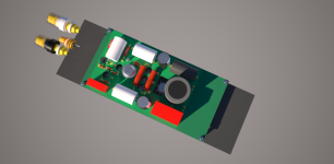
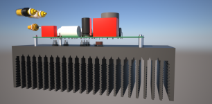
... the progress for today...
Dear Vladimir can you provide please the schematics for the +28VDc and -9VDC (cap multipliers and so)?
Regards,
Jean-Paul
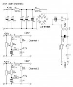
For +28V, I propose something like this. For -9V, another winding and source follower with p-type mosfet.
Attachments
Last edited:
Hello Vladimir,
thanks you for the schematics.
Do you have a replacement for the 2SK1259?
And do you have the -9VDC supply schematics as wired in your amplifier (I don´t want to reinvent the wheel)?
Regards,
Jean-Paul
IRFP240 could be a replacement for 2SK1529. For -9V supply I used Ge transistors connected as diodes at bridge rectifier. Actually one can use source followers by analogy to +28V, and small soft recovery ultrafast diodes at the bridge. Even more, I would propose to try 5W zener for 9V. Do not afraid to use another good variants.
You use some Ge-Diode for rectifying. Are they available (what is the value for them?)? I replace them with DSS16 Schottky-Diode! It is ok?
Go with DSS16, seems to be a good choice.
Ge diodes that are available still are
D302 (1A, 200V)
D303 (3A, 150V)
D304 (5A, 150V)
D305 (10A, 50V)
Also one could use Ge power transistors as diodes (base and collector shorted)
- Status
- This old topic is closed. If you want to reopen this topic, contact a moderator using the "Report Post" button.
- Home
- Amplifiers
- Solid State
- NoGNFB integrated amp with Ge transistors at output