I was looking for a amplifier with great THD results, but also not that complex.
Because I will only use it for measurements (THD, tests, etc etc).
5W-8ohm/10W-4ohm would be enough.
(maybe I will go to 10W @ 8ohm)
The idea is very simple, use a decent opamp (opa134/lm4562 etc etc) and put a current amplifier behind it.
I first tried a Mosfet follower but found out that the currect was very big.
So I tried a darlington pair, and I think it's better.
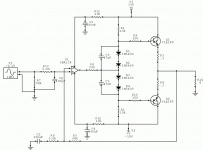
This is simulated with the ZTX605/705. I think the ZTX651/751 would be better. (because of the current)
I have a few questions.
Is this going to work this way ?
What does C2 (1uF) do exactly ? (in the simulation it reduces the THD enormous ! )
Are there any other improvements ?
Because I will only use it for measurements (THD, tests, etc etc).
5W-8ohm/10W-4ohm would be enough.
(maybe I will go to 10W @ 8ohm)
The idea is very simple, use a decent opamp (opa134/lm4562 etc etc) and put a current amplifier behind it.
I first tried a Mosfet follower but found out that the currect was very big.
So I tried a darlington pair, and I think it's better.
This is simulated with the ZTX605/705. I think the ZTX651/751 would be better. (because of the current)
I have a few questions.
Is this going to work this way ?
What does C2 (1uF) do exactly ? (in the simulation it reduces the THD enormous ! )
Are there any other improvements ?
Last edited:
well...
I may be wrong, but I think your diodes are backwards, and you may find that a third one will lower the distortion further...
IIUC they are to provide a some bias voltage for the output transistors, and as they are drawn they are reversed biased by R4 and R5, and therefore not having the desired effect. I think perhaps you can see the effect of the excess bias voltage in the idle current of 635ma, shown on the meters for the voltage rails.
If you connect the output of the opamp to the junction of the diodes, reversed, you can avoid loading the opamp at idle and depending on it's characteristics things will be different. Adding a resistor from the output of the opamp to one rail or the other will force it to operate with the output in class A. Not all opamps like this, and you may get different results depending out which rail and the value of the resistor.
The cap across the diodes helps discharge the base current from the output transistor that is turning off, without it the output is much slower in transition from full one direction to the other.
HTH
Stuart
Thank you for your comments, let's change it and look at the results ")
I thought that the ZTX651/751 where also Darlington,s but I think that's a mistake.
are there other Darlington pairs that can easy deliver 2-3A ?
I think it is not necessary to operate the opamp in class-a because the THD of the opamp is also very low.
Maybe a improvement later
edit:
The diodes are connected the right way. If I connect them backwards the THD is much higher.
There is also no difference between 2 or 3 diodes in the simulation. (but that's not the real world)
What kind of heatsink can I use ?
not so fast...
Unless I am missing a key point...
The distortion may be higher with the diodes reversed, but the output transistors will not be passing >600ma of current. I think what you have right now is a very improperly biased classB amp. It only works because the models for the transistors are unrealistic and the bases are fed from 100k resistors.
What is the idle current with the diodes reversed, I think it will drop to almost zero, indicating a 'normal' class B amp, then you have to bias the output transistors properly to minimize the crossover distortion. If you want to make an amp with a classA output stage you need to arrange the bias conditions with more control and less dependence on the sims transistor model.
Good luck
Stuart
What you are doing here is similar to this:
http://sound.westhost.com/project76.htm
and this
http://sound.westhost.com/project113.htm
In your diagram, the diodes are the wrong way around - the circuit would not work in real life.
I've had good results with using a diamond buffer on the end of an opamp. See for example Per-Anders Sjöström's QRV05 circuit.
Eline output transistors that can dissipate 1.5W, if you can keep them at 25degC, will not be man enough for an 8W output.
With ClassAB amplifiers it is usual to have the output devices able to dissipate 2 to 3 times the maximum output power. This would indicate you need 15 to 30W devices.
With ClassAB amplifiers it is usual to have the output devices able to dissipate 2 to 3 times the maximum output power. This would indicate you need 15 to 30W devices.
the diodes are the wrong way around.
think about the actual function of the diodes.
you can certainly build it (instead of simulating), but we would recommend a current limited power supply and some spare output devices.
also, don't hook up your good speakers just yet either ...
mlloyd1
think about the actual function of the diodes.
you can certainly build it (instead of simulating), but we would recommend a current limited power supply and some spare output devices.
also, don't hook up your good speakers just yet either ...
mlloyd1
Those Zetex devices would die a horrible death as output devices. The low distortion you see with the diodes wrong way round is because the outputs are operating in class A. Those poor Zetex darlingtons are cooking with 9+ watts of heat on them. Think they are only good for 2 watts at most, haven't looked them up but I think thats right. With the diodes the correct way round the outputs idle at cutoff which will show as very high crossover distortion, thus the reason you see a huge increase in your distortion sims. You need 4 diodes to get a correct forward bias using darlingtons. Remember a darlington is two transistors stacked together so they have two BE drops per device. Attached is a circuit that would be a much better starting point for your experiments.
Attachments
it's like there's...
...an echo chamber here or something...
Your idea is sound, but you need to understand the limitations of the simulation environment vs a real construction. There are physical boundaries the simulation is not honoring, in this case, the output transistors being cooked etc.
Even if you can find a huge set of darlington output devices, Motorola have 300w devices I think, they will not behave the way the simulation suggests they should. The pair will have dissimilar gain, Vbe etc that will seriously compromise the real world behavior of the amp.
If you are willing to look around a little more you can easily find a stable output stage onto which you can graft the opamp input. If simple is the goal, Class A will probably get you the best bang for your part count, but you need more power and heatsinks. Class B will need more attention to biasing detail, but has lower power needs and smaller heatsinks.
From the Passlabs arena you might try an output mosfet loaded by a CCS; very easy to get stable, simulates well and adds very little distortion as long as you set the CCS properly...
HTH
Stuart
This amp will most likely work, but having built a similiar one,
it will sound like garbage.
After having a heated discussion with our beloved carlos (DX)
about how crappy a darlington amp sounded, I decided to build
this:elector darlington amp
on a veroboard using 100w sanken devices from a dead sony
HT unit. The elector amp has a real Vbias generator and
LPT, so I figured it would sound OK.
Once it was built I almost conceded to carlos's opinions...
crossover distortion, harsh sound..
I was discouraged.
But, later, still wanting to give the sanken devices a home,
I came across the LM4702 and this circuit:LM4702 darlington amp
Much to my surprise, it worked and sounded very good!!
playing around, I subbed tip120/125's, a Real EF OP
section, and various other junkbox outputs into my prototype
and they all sounded better than the HT receiver.(same speakers,
same music.)
In conclusion, for the same price as a couple of HQ op-amps
the LM4702 (7-8 US$$) will give you stereo you can use and
enjoy while giving a home to all your orphaned darlingtons.
BTW.. In a future DIY project I'm thinking of a 4 OP device EF or
CFP (maybe even Thermal trak) variation of the 4702.
OS
it will sound like garbage.
After having a heated discussion with our beloved carlos (DX)
about how crappy a darlington amp sounded, I decided to build
this:elector darlington amp
on a veroboard using 100w sanken devices from a dead sony
HT unit. The elector amp has a real Vbias generator and
LPT, so I figured it would sound OK.
Once it was built I almost conceded to carlos's opinions...
crossover distortion, harsh sound..
I was discouraged.But, later, still wanting to give the sanken devices a home,
I came across the LM4702 and this circuit:LM4702 darlington amp
Much to my surprise, it worked and sounded very good!!
playing around, I subbed tip120/125's, a Real EF OP
section, and various other junkbox outputs into my prototype
and they all sounded better than the HT receiver.(same speakers,
same music.)
In conclusion, for the same price as a couple of HQ op-amps
the LM4702 (7-8 US$$) will give you stereo you can use and
enjoy while giving a home to all your orphaned darlingtons.
BTW.. In a future DIY project I'm thinking of a 4 OP device EF or
CFP (maybe even Thermal trak) variation of the 4702.
OS
Ok, let's put something straight.
The amplifier I'm looking for IS NOT for listening.
The amplifier is for testing purpose for different kind of things, with a few goals.
A maximum power of around 5-10W @ 8ohm, low distortion that can be possible (I hope around 0,0007% @ 1kHz) and hopefully simple to build and mono (one channel)
I mailed to the inventors of the Extrema Class-A amplifier (with really really good THD results) if they had an idea.
(Bruno Putzeys)
He came with the idea to use an great performing opamp, like LM4562 or OPA134 or so, followed by an class-a current follower.
I first tried a Mosfet amplifier, like this :
http://tweakers.net/ext/f/eftQ80C6cuGzTn6dHEByfC4R/full.png
But discovered that there was a lot of current needed and the output power was very low.
So I looked further for a better design and find the Darlington circuit.
The new circuit is this one:
Most chipamps (I have build a lot of them) do not have very well THD results. I mean for testing, for listening they will be fine.
And forget the Zetex it was just for the example
Another question that I have, is what output transistors can I use. Will the BD536 (or so) be fine ?
The amplifier I'm looking for IS NOT for listening.
The amplifier is for testing purpose for different kind of things, with a few goals.
A maximum power of around 5-10W @ 8ohm, low distortion that can be possible (I hope around 0,0007% @ 1kHz) and hopefully simple to build and mono (one channel)
I mailed to the inventors of the Extrema Class-A amplifier (with really really good THD results) if they had an idea.
(Bruno Putzeys)
He came with the idea to use an great performing opamp, like LM4562 or OPA134 or so, followed by an class-a current follower.
I first tried a Mosfet amplifier, like this :
http://tweakers.net/ext/f/eftQ80C6cuGzTn6dHEByfC4R/full.png
But discovered that there was a lot of current needed and the output power was very low.
So I looked further for a better design and find the Darlington circuit.
The new circuit is this one:
An externally hosted image should be here but it was not working when we last tested it.
Most chipamps (I have build a lot of them) do not have very well THD results. I mean for testing, for listening they will be fine.
And forget the Zetex it was just for the example
Another question that I have, is what output transistors can I use. Will the BD536 (or so) be fine ?
The lm4702 is not really a chipamp, it is a dedicated LPT/VAS
designed for driving a wide array of OP stages.
I think a carefully designed one could exceed discreet
performance because all is on one mask(better matching).
Internally it is a fully complimentary differential amp
(leach front end on a chip) capable of .001% thd or better
while still being affordable.
Definitely not a lm3886 (which is a good amp) and very good as a
test amp (i've used one as a motor controller), real low part
count and dirt cheap. An if you can listen to it as well,
a free benefit.
BTW - In the motor controller I run it at +-24v still works great.
But why should I use a (stereo) LM4702?
It's very much a boosted opamp, usable for high powers.
But I only need 10W.
I also need a Darlington/transistor or mosfet to drive a speaker from it?
I do not see the difference but only the power (I can better say the output voltage which is higher)
Or do I miss a point ?
It's very much a boosted opamp, usable for high powers.
But I only need 10W.
I also need a Darlington/transistor or mosfet to drive a speaker from it?
I do not see the difference but only the power (I can better say the output voltage which is higher)
Or do I miss a point ?
Doug Self posts a series of papers on building a low distortion discrete power amplifier that achieves this figure in the midband. Essential reading or buy the book.b_force said:low distortion that can be possible (I hope around 0,0007% @ 1kHz) and hopefully simple to build and mono (one channel)
Many amps do not aim anywhere near that low level of distortion and are reportedly all the better for it.
A few, very specialised, amplifiers can better this but they are fairly complicated compared to Self's Blameless, which in turn is massively more complicated than an opamp and output stage.
Go read Self and Leach and Pass and ESP before you make a decision. Be informed.
I have designed and built a low power test amp for similar purposes as what you want. There are some flaws in your design both for practical operation and lowering distortion, the output stage is lacking a local feedback mechanism and the bias string is not implemented very well nor does it have very good PSRR.
Have a look at my class-a multi-purpose amp project www.readresearch.co.uk but bear in mind that 10W class-a is going to take big output devices and very big heatsink.
Have a look at my class-a multi-purpose amp project www.readresearch.co.uk but bear in mind that 10W class-a is going to take big output devices and very big heatsink.
Yes I've read both articles earlier.
But when I'd read them, I was asking myself. Ok it is difficult to get that amount of THD, but in those days when the articles where written there weren't opamp that can perform that great.
If you look to the LM4562 (or similar) for example. I think you can say that it is almost impossible to get those numbers is your are building everything discrete.
I mean if you are plan to build something simple and with low power. If you plan to build a fully operating amplifier (with more power) there are other techniques. (and discrete can be the solution)
Is it so impossible to build a very well performing current stage to deliver the correct amount of current to your speaker/load ?
I'll also try to explain why I need an amplifier like this.
I'm studying bachelor of engineering in Physics. There are some psychical questions I like to research (and hopefully to answer), but to get good results I think I need a very well performing amplifier so the noise level (THD etc) is as low as it can be.
That's also the whole point, we do get a little bit of electronics, but not that much as if you are studying electronics.
Hopefully it will now be clear where the amplifier will be used for. So not for listening !
So let's repeat the question again.
Will it impossible to build a simple amplifier with a THD around 0,0007% @ 1kHZ with a very well performing opamp + current follower?
Because otherwise I'll put my energy in something else
(there are some more difficult low power class-a amplifier as a kit, but more expensive)
@ richie00boy 5W @ 8ohm will be fine (10W is more flexible).
Active cooling (like a big copper CPU heatsink + fan) will be ok if it doesn't has a negative effect on the performing of the amp.
Will it impossible to build a simple amplifier with a THD around 0,0007% @ 1kHZ with a very well performing opamp + current follower?
In short: no.
You need way more electronics knowledge to go that low.
That's a level where also wiring and actual building of the amp (pcb-layout) is pretty critical. And of course you need a distortion analyzer to verify this performance - and I guess you don't have access to one.
But let that does not stop you
Have fun, Hannes
EDIT: by the way, you will need also a very good distortion analyzer, as you're already testing its signal generator near its limits.
Oh another idea: if you only need a low THD sine wave generator you can look for Walt Jungs articles. But that beast won't put out multiple watts.
You find the article somewhere here
http://waltjung.org/Library.html
But don't forget what I wrote about these low THD-levels; you would still need an Audio Precision or HP THD-analyzer to verify that performance. Layout and wiring is critical.
Have fun, Hannes
You find the article somewhere here
http://waltjung.org/Library.html
But don't forget what I wrote about these low THD-levels; you would still need an Audio Precision or HP THD-analyzer to verify that performance. Layout and wiring is critical.
Have fun, Hannes
- Status
- This old topic is closed. If you want to reopen this topic, contact a moderator using the "Report Post" button.
- Home
- Amplifiers
- Solid State
- Little opamp/darlington amplifier