Could be a bit much if class AB is what your shooting for, otherwise just a bit of wasted heat, lowering the potential output and SOA from these transistors. Can you not get 15Vp output? If efficiency is not a factor, I guess 12.5Vp is fine. If 12.5Vp output is acceptable, why do you not just use an emitter follower? It would be more stable......in the real world. As you know, with the Darlington follower, you lose 2Vbe drops, or 1.2V from the signal. IMO, the unity gain CFP can have stability problems unless compensated. I remember I had problems getting it to work without gain. IMHO, the CFP circuit is inferior anyway, for more than one reason.........OOoooo man, I may strike a nerve with that statement.......
As you know, with the Darlington follower, you lose 2Vbe drops, or 1.2V from the signal. IMO, the unity gain CFP can have stability problems unless compensated. I remember I had problems getting it to work without gain. IMHO, the CFP circuit is inferior anyway, for more than one reason.........OOoooo man, I may strike a nerve with that statement.......Like I said, 5W @ 8ohm would be the minimum, but I reaaaly prefer 10W @ 8ohm.
If the transistors would be the problem, which can I take to make it work ?
Or are there other current amplifiers which van perform very very well ?
(or tried to use a mosfet stage ones, but it needed current like mad)
The only goal is 10W 8ohm and THD as low as possible
Then a came whit this circuit, thought it would work fine.
So if there are better (simpler) options, please let know
I'm not shooting for A/B, B or A (or D), just something that will perform well.
10Wrms/8 Ohms = 1.25 SQRT 1.25 = 1.12A rms; 1.12 X SQRT 2 = 1.58 or ~1.6A peak. 1.6A X 8 Ohms = 12.8Vp. If better quality is desired, then class A would be a good way to go because the transistors are never turned off. Transistor turn off creates quite a bit of distortion. If full class A, then 1.6A bias ought to be enough. 1.6A X 15V = 24W from each transistor, which is pushing it a little far for these devices for the SOA, but the simulator won't tell you that. But you don't have to go fully class A, I suppose.
If you choose to use a Darlington follower, then it would require an AC drive of 14Vp from the op-amp to have 12.8V peak at the output. You should be able to get this from the op amp I would think. You would certainly have to have Vbe thermal compensation via a Vbe multiplier though. The CFP may also need thermal compensation. That would be accomplished by physically mounting D1 & D2 with Q1 & Q2 since in a CFP, it is the drivers that should be compensated......in the real world. In simulator, it may not make a difference. In a real transistor, Vbe decreases with increase of temperature.
IMHO, one of the problems with CFP is that the load is driven by the dependent current source part of the transistor, that being the collector. This tends to make the circuit a bit load dependent wrt operation and stability. A speaker is a far cry from a resistor. At some frequencies the current lags the voltage, and at others, the current leads the voltage. Also, the magnitude may vary as well, sometimes less than 8 Ohms, sometimes more, depending on frequency and speaker. They are all different to some degree. Hardly representable by a simple resistor. The CFP is a viable circuit and is used often, but the emitter follower tends to be more immune to these variable parameters.
Edit:BD535/536 appears to have a fairly low current gain (Hfe). I have used D44/45 transistors. They are quite linear and have a higher Hfe. This may allow you to use them as a simple follower without the Darlington drivers. The op amp may be able to drive the bases of these directly since your only looking for 1.6A peak. Less parts, simpler design.
If you choose to use a Darlington follower, then it would require an AC drive of 14Vp from the op-amp to have 12.8V peak at the output. You should be able to get this from the op amp I would think. You would certainly have to have Vbe thermal compensation via a Vbe multiplier though. The CFP may also need thermal compensation. That would be accomplished by physically mounting D1 & D2 with Q1 & Q2 since in a CFP, it is the drivers that should be compensated......in the real world.
In simulator, it may not make a difference. In a real transistor, Vbe decreases with increase of temperature.IMHO, one of the problems with CFP is that the load is driven by the dependent current source part of the transistor, that being the collector. This tends to make the circuit a bit load dependent wrt operation and stability. A speaker is a far cry from a resistor. At some frequencies the current lags the voltage, and at others, the current leads the voltage. Also, the magnitude may vary as well, sometimes less than 8 Ohms, sometimes more, depending on frequency and speaker. They are all different to some degree. Hardly representable by a simple resistor.
The CFP is a viable circuit and is used often, but the emitter follower tends to be more immune to these variable parameters. Edit:BD535/536 appears to have a fairly low current gain (Hfe). I have used D44/45 transistors. They are quite linear and have a higher Hfe. This may allow you to use them as a simple follower without the Darlington drivers. The op amp may be able to drive the bases of these directly since your only looking for 1.6A peak. Less parts, simpler design.
I would bet that the op amp has enough output current to drive the bases of a transistor like D44/45 to and Ic of 1.6A. This coupled with a Vbe multiplier might just work. Using the BD139 as the multiplier, mounted with the outputs, it will decrease the Vbe bias as temperature increases keeping them from thermal runaway and meltdown.
The idea of the current source (the J-fet or whatever CCS you want to use, but a CCS gets no simpler than a self bias J-fet ) is so that the op amp will see a more constant impedance, and not have to drive as much change in current as if it was a resistor. The op amp will like this more.
The idea of the current source (the J-fet or whatever CCS you want to use, but a CCS gets no simpler than a self bias J-fet
) is so that the op amp will see a more constant impedance, and not have to drive as much change in current as if it was a resistor. The op amp will like this more.Attachments
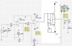
The output emitter resistors about 0.3 Ohms, the pot maybe 470 Ohms, or better yet, 200 Ohms pot in series with 330 Ohms, and the collector to base resistor on the multiplier about 470 Ohms. This is an at a glance guess. Experiment and see. The J-fet resistor depends on the J-fet, but a few mA or so. Measure Vgs @ a few mA, Vgs/Id = R.
mmmm, the total THD is very dependent from the capacitor.
Which value is reasonable ? 10uF ?
edit:
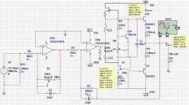
Here the schematic and measurements:
(I just picked a jfet of the standard library)
Which value is reasonable ? 10uF ?
edit:
Here the schematic and measurements:
An externally hosted image should be here but it was not working when we last tested it.
(I just picked a jfet of the standard library)
What value simulates best? I am thinking 1uf - 4.7uf. That capacitor provides AC coupling between the bases of the outputs. I would shoot for about 30-80mA bias in the outputs. More current may lead to less crossover distortion, but comes at the price of more heat. Does the pot allow you to adjust for this range?
Try placing a 330 Ohm resistor in series with the 220 Ohm pot. Right now, it appears that the BD139 is cutoff. The idea is that it conducts more to reduce the bias in the outputs. Adjust the pot (increase value) until the outputs are cutoff, and then reduce the value until you get about 50mA of conduction in the outputs. This is the procedure you would take if you were building a real circuit.
In series with the pot, between the base and emitter of the BD139. This will allow a more fine tuned adjustment of the bias of the BD139, and of the output bias. If it is out of range, play with the values of that one and R4. Remember, to turn the outputs off, the BD139 must be turned on more. With just the 220 Ohm resistor, you can't get 0.6V across it to turn on the BD139.
As the outputs get hotter, thier Vbe decreases. If the bias is static, they will begin to conduct more current as they are heated. This in turn makes thier Vbe decrease further, resulting in more current and more heat, and so on until they self destruct. The BD139, mounted on the heatsink with the outputs, will be heated by the outputs and in turn conducts more. This pulls the bases of the outputs closer together wrt temperature, thus keeping the bias of the outputs stable as they are heated. Turn off the BD139, turn on the outputs, vice vera, it is inversly proportional.
As the outputs get hotter, thier Vbe decreases. If the bias is static, they will begin to conduct more current as they are heated. This in turn makes thier Vbe decrease further, resulting in more current and more heat, and so on until they self destruct. The BD139, mounted on the heatsink with the outputs, will be heated by the outputs and in turn conducts more. This pulls the bases of the outputs closer together wrt temperature, thus keeping the bias of the outputs stable as they are heated. Turn off the BD139, turn on the outputs, vice vera, it is inversly proportional.
If Q2 is conducting properly, there shouldn't be 500-600mA in the outputs. In fact, you should be able to increase the pot to the maximum setting and completely turn off the outputs. (turn on BD139) This will increase distortion, but you should be able to decrease the pot to some value and see the output's bias increase. You may need to play with the resistor values biasing the BD139. But, there should be about 1.2V between the bases of the outputs. There will be 0.6V between the base and emitter of the BD139. This leaves 0.6V between the collector and base. The resistor values should be about the same, but you need some way to adjust the resistance between the base and emitter by 10-20% so you can control the bias in the outputs.
It looks like the D44/45 will only work with a VCC of ±20V (or higher)
But the circuit is very difficult to setup.
If a change a value (a resistor or the capacitor for example) the high freq will be better, but the low (50Hz or so) will be worse etc etc....
But if we go back to the beginning.
I don't know what's wrong with the circuit from ESP.
He build the circuit and it worked fine, so where is the problem ?

- Status
- This old topic is closed. If you want to reopen this topic, contact a moderator using the "Report Post" button.
- Home
- Amplifiers
- Solid State
- Little opamp/darlington amplifier