I received in the kit 8x 10nK400 caps, 2x BR84 rectifiers, 4x 10000uF A7088 caps (very expensive!), and 4x 10000uF 8925E caps, but I'm not sure which circuit exactly he had in mind with such components.
The transformers I have: 2x 40-0-40v / 3.6A *
Hope I made this understandable, but most PSU's are very simple.
Lamir
* is that 4 x 3.6A in total? that's insanely high A.
The transformers I have: 2x 40-0-40v / 3.6A *
Hope I made this understandable, but most PSU's are very simple.
Lamir
* is that 4 x 3.6A in total? that's insanely high A.
* is that 4 x 3.6A in total? that's insanely high A.
You can build two +/-56VDC supplies at approx 2.3A
You can build two +/-56VDC supplies at approx 2.3A
You haven't mentioned the voltage rating of the capacitors.
Surely you bought the kit for a specific reason ?
First of all thank you for your answers!
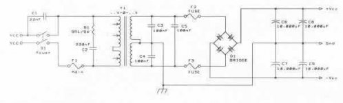
That's interesting, I was expecting something more like this:
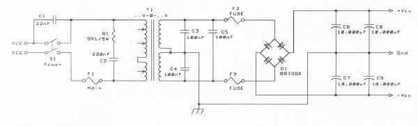 From this page.
I can only wonder why the kit includes 2 different cap types, perhaps because their combined speed in parallel will be their average speeds (cheaper than 4 very fast caps I presume).
Those components woulod make a simple basic PSU.
The 10000uF caps are mounted in pairs across the DC outputs of the bridge.
The smaller caps are mounted across the diodes of the bridge.
That's interesting, I was expecting something more like this:
The caps are rated 63v, which is more than the 40v rating of the transformer by a safe margin. It's for the M400 kit, H/D Amp said minimum voltage per amplifier is +- 35vdc and maximum +-58v and the amps will draw 3A. It's a perfect dual mono design.You haven't mentioned the voltage rating of the capacitors.
Surely you bought the kit for a specific reason ?
I can only wonder why the kit includes 2 different cap types, perhaps because their combined speed in parallel will be their average speeds (cheaper than 4 very fast caps I presume).
Attachments
Last edited:
The secondaries have 8 wires: 2 x 40v, 2 x 15v. The 15v aren't useful for the amp since they're only 0.4A, but I could use it for the LED - one diode, a 270ohm resistor, and I should get an ON led..?
It's DUAL MONO, so the above is doubled, yes. I apologize I didn't mentioned that in the first post.
It's DUAL MONO, so the above is doubled, yes. I apologize I didn't mentioned that in the first post.
8 wires equals four windings.
Looks like you have a dual 40Vac secondary and a dual 15Vac secondary.
A centre tapped 40-0-40Vac secondary has three wires.
two sets of these would need six wires.
Add on four wires for the dual 15Vac secondary and you are up to 10wires.
What have you really got?
Looks like you have a dual 40Vac secondary and a dual 15Vac secondary.
A centre tapped 40-0-40Vac secondary has three wires.
two sets of these would need six wires.
Add on four wires for the dual 15Vac secondary and you are up to 10wires.
What have you really got?
That's not a good psu for audio. AndrewT will sort you out.That's interesting, I was expecting something more like this:
Also, for safety, always put the mains fuse as the first thing your power cord connects to. Never after the power switch.
Don't take too much notice of what appears on the TNT Audio site. They appear to believe that scattering capacitors around will fix problems (possibly non-problems) yet are not too bothered about putting grounds in the right place.
I am not quite clear what the point of this thread is. Given a normal set of PSU components one can make a normal PSU. The usual mistakes people make when building these do not come from the circuit but from implementation details, such as grounding and wire twisting, so the circuit more or less writes itself.
I am not quite clear what the point of this thread is. Given a normal set of PSU components one can make a normal PSU. The usual mistakes people make when building these do not come from the circuit but from implementation details, such as grounding and wire twisting, so the circuit more or less writes itself.
Why is it not good? C1, C2, and R1 are there for no reason?That's not a good psu for audio. AndrewT will sort you out.
First thing to happen when I connected the (a single chan) PSU to mains: blown F7A fuse. I'll add a soft start, it'll make it safer too.Also, for safety, always put the mains fuse as the first thing your power cord connects to. Never after the power switch.
For me it's a first power amp and I'm still testing the water. I have the parts from a kit, but have no experience in PSU's to know which circuit up to the standards they could be used for (until #3 posted a circuit).I am not quite clear what the point of this thread is. Given a normal set of PSU components one can make a normal PSU. The usual mistakes people make when building these do not come from the circuit but from implementation details, such as grounding and wire twisting, so the circuit more or less writes itself.
Transformers: 2 x 40v/3.6A , 2 x 15v/0.4A , so total 2 primary wires, 8 secondary wires.Please answer posts #9 and #5.
Transformer wires, what have you got ?
Capacitors, what voltages ?
These informations would avoid wasting time and efforts.
Capacitors 63V rated.
What's wrong with that? Wiring the + and - voltages with the same cap types and doing the same on both chans make the circuits at least equal.Two different types of caps looks like audio-foolery to me. You would expect some form of CRC or CLC with more than one reservoir cap. per rail.
Edit: I think I see your point on, it's similar to connecting two batteries in parallel...
Last edited:
8 wires equals four windings.
Looks like you have a dual 40Vac secondary and a dual 15Vac secondary.
...........................
What have you really got?
8 secondary wires confirm two sets of dual secondaries...................
Transformers: 2 x 40v/3.6A , 2 x 15v/0.4A , so total 2 primary wires, 8 secondary wires.
Capacitors 63V rated.............
One pair of dual 40Vac secondaries will give you a dual polarity high power supply for your amplifier/s. The other pair of dual 15Vac secondaries will give you a supply for all your auxiliaries and active filters, pre-amps, protections etc.
Last edited:
Those components woulod make a simple basic PSU.
The 10000uF caps are mounted in pairs across the DC outputs of the bridge.
The smaller caps are mounted across the diodes of the bridge.
I hope it doesn't seem like rude self-bump, but to refine the question and given there are 2 different types of caps (4x 10000uF A7088 63v caps, 4x 10000uF 8925E 63v caps), what could possibly be the psu design which makes the best of them? These psu parts came with the M400 H/D amp kit, but should they be connected two different types in parallel?
I do not understand two sets of 10 000uF 63v caps. I was unable to find the caracteritics of those caps to see what difference.
4 x 10 000uF 63v caps is consistent with 2 x 40v windings. This would make a +56v & -56v supply with 1 rectifier bridge and 2 x 20 000 uF caps.
The second set of 4 x 10 000uF 63v is not consistent with 2 x 15v windings. This would make a +21v & -21v supplier that requires no better than 25v caps.
Could be there are other configurations I did not guess....
I hope it doesn't seem like rude self-bump, but to refine the question and given there are 2 different types of caps (4x 10000uF A7088 63v caps, 4x 10000uF 8925E 63v caps), what could possibly be the psu design which makes the best of them? These psu parts came with the M400 H/D amp kit, but should they be connected two different types in parallel?
Try to keep the PSU symmetrical. ie use one of each type on each rail in parallel with one of the others. I would add a small resistor between them in CRC configuration, something like 0R1 3W.
Making good use of existing parts
At first, a little ironic:
Although at your tranny there are four useful connections instead of a center tapped three, it´s NOT the best idea to build two voltage doubler supplies (*) of them... just to "get good / better channel separation" by galvanic isolation.")
[(*) If you don´t know yet, with a classic "Delon type" voltage doubler you could get out a complete symmetric supply --- of only TWO secondary connections.
You would only have to "declare" the point between the two caps (which also is one of the seco. AC-connections - really, directly) as your "new GND", but...
You also would need to (at least) double the capacitance, cause of the inherent halfed voltage ripple frequency. And the losses in the capacitors would be relatively high. So this ídea is not as good - although possible.
Please don´t really think about it now.]
To get serious:
The best you could do is (imho) to ignore your separate windings, and make a center tap 40-0-40. Therefore you have to find out the right winding direction, if you don´t already know it. (Do you?)
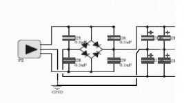
Next step would be to build two parallel and identical "double-center-tap rectifiers" (#), from your two rect. bridges. And put one of the little 10nK400 caps parallel to every rect. diode, as @KatieandDad suggested. Picture of (#) can be found here, at the right side:
http://www.joretronik.de/Web_NT_Buch/bilder/b2_3_a_b.gif
One great advantage of this possibility is, that there is only half the diode loss, than by using one complete bridge rect. per rail. Ok... Now you have the base for two symmetrical supplies, exactly what you wanted.
At this point i nearly fully agree to post 19, that you should "spread out" your different electrolytics equally into the two supplies, and also place them symmetrically (topologically identical, and in series), into the rails.
If I were you, I would place the better ones (normally related to their ESR, but I didn´t find data for 8925E - so I consider the A7088 to BE better...) near the amp, the "worse" of them near the tranny.
So far so good. We´re nearly finished now. But let me add something else:
For a tranny of this size a soft-start is normally not needed.
But you should take care of the correct placement and dimensioning of fuses. Some trannys already have a thermal fuse, hidden within (once triggered, it´s over). Much more seldom there are reverseable switches. So if you don´t know, what´s really up there, it´s a good idea, to place a fuse into the primary! (Do you know?)
If you know, there IS such a "overload = permanent damage"-switch... you can choose different methods to avoid triggering. The result is nearly similar, no matter what one would do.
If you prefer a sluggish one, dimensioned relatively exactly to the trannys rated current, or if you want to use a faster one, which could be rated for a very little more - with a real "killswitch" there are no significant degrees of freedom, and there´s no real variable choice of "overload - or not - and how far"...
If there´s a reverseable one,or,much better, NO ONE, it´s a completely different story.
But completely independent of this issue, there are also fuses needed to place into the rails, exactly before they reach the amplifier output stage... (naturally, except, you trust the current limit of the amps - is there any? - soooo far, that you ignore me here).
One more advice: I would not only place the better caps near the amps, but (referring again to post 19) i suggest to place XXX µH inductors (instead of resistors) between the rail-poles of the different e-lytic types. Inductors can have very low DC-resistance, though their better filtering action.
Please, think of this idea. Good dimensioned inductors would allow a much more dynamical bass, though they clean up the rail very much. Because they mainly have AC-resistance (if you choose the right type...)
They should have an adequate current rating at their data sheet, that´s really important. And... they should not be TOO big (neither their inductance, nor their geometry - and this goes "hand in hand", at a given current rating).
If you decide to follow my advice (i would be glad, if you do ... especially related to "my" inductor advice (smile)), you can continue to ask here - i´m sure, help will arrive you.
Greets, Fred
(P.S.: I was writing soooo much, because i´m only seldomly here at the board, and seldomly surfing the net, too. Good luck...)
At first, a little ironic:
Although at your tranny there are four useful connections instead of a center tapped three, it´s NOT the best idea to build two voltage doubler supplies (*) of them... just to "get good / better channel separation" by galvanic isolation.
[(*) If you don´t know yet, with a classic "Delon type" voltage doubler you could get out a complete symmetric supply --- of only TWO secondary connections.
You would only have to "declare" the point between the two caps (which also is one of the seco. AC-connections - really, directly) as your "new GND", but...
You also would need to (at least) double the capacitance, cause of the inherent halfed voltage ripple frequency. And the losses in the capacitors would be relatively high. So this ídea is not as good - although possible.
Please don´t really think about it now.]
To get serious:
The best you could do is (imho) to ignore your separate windings, and make a center tap 40-0-40. Therefore you have to find out the right winding direction, if you don´t already know it. (Do you?)
Next step would be to build two parallel and identical "double-center-tap rectifiers" (#), from your two rect. bridges. And put one of the little 10nK400 caps parallel to every rect. diode, as @KatieandDad suggested. Picture of (#) can be found here, at the right side:
http://www.joretronik.de/Web_NT_Buch/bilder/b2_3_a_b.gif
One great advantage of this possibility is, that there is only half the diode loss, than by using one complete bridge rect. per rail. Ok... Now you have the base for two symmetrical supplies, exactly what you wanted.
At this point i nearly fully agree to post 19, that you should "spread out" your different electrolytics equally into the two supplies, and also place them symmetrically (topologically identical, and in series), into the rails.
If I were you, I would place the better ones (normally related to their ESR, but I didn´t find data for 8925E - so I consider the A7088 to BE better...) near the amp, the "worse" of them near the tranny.
So far so good. We´re nearly finished now. But let me add something else:
For a tranny of this size a soft-start is normally not needed.
But you should take care of the correct placement and dimensioning of fuses. Some trannys already have a thermal fuse, hidden within (once triggered, it´s over). Much more seldom there are reverseable switches. So if you don´t know, what´s really up there, it´s a good idea, to place a fuse into the primary! (Do you know?)
If you know, there IS such a "overload = permanent damage"-switch... you can choose different methods to avoid triggering. The result is nearly similar, no matter what one would do.
If you prefer a sluggish one, dimensioned relatively exactly to the trannys rated current, or if you want to use a faster one, which could be rated for a very little more - with a real "killswitch" there are no significant degrees of freedom, and there´s no real variable choice of "overload - or not - and how far"...
If there´s a reverseable one,or,much better, NO ONE, it´s a completely different story.
But completely independent of this issue, there are also fuses needed to place into the rails, exactly before they reach the amplifier output stage... (naturally, except, you trust the current limit of the amps - is there any? - soooo far, that you ignore me here).
One more advice: I would not only place the better caps near the amps, but (referring again to post 19) i suggest to place XXX µH inductors (instead of resistors) between the rail-poles of the different e-lytic types. Inductors can have very low DC-resistance, though their better filtering action.
Please, think of this idea. Good dimensioned inductors would allow a much more dynamical bass, though they clean up the rail very much. Because they mainly have AC-resistance (if you choose the right type...)
They should have an adequate current rating at their data sheet, that´s really important. And... they should not be TOO big (neither their inductance, nor their geometry - and this goes "hand in hand", at a given current rating).
If you decide to follow my advice (i would be glad, if you do ... especially related to "my" inductor advice (smile)), you can continue to ask here - i´m sure, help will arrive you.
Greets, Fred
(P.S.: I was writing soooo much, because i´m only seldomly here at the board, and seldomly surfing the net, too. Good luck...)
- Status
- This old topic is closed. If you want to reopen this topic, contact a moderator using the "Report Post" button.
- Home
- Amplifiers
- Power Supplies
- I have the parts of a PSU kit, but don't have the schematic... which should I build?