At first, a little ironic:
<snip>
I don't understand what do you mean by "near". They are very close to each other, 2cm of wire.I would place the better ones near the amp, the "worse" of them near the tranny.
I already ordered a soft start.For a tranny of this size a soft-start is normally not needed.
Do you have any schematic or a source for that? I never saw such a circuit.I would not only place the better caps near the amps, but (referring again to post 19) i suggest to place XXX µH inductors (instead of resistors) between the rail-poles of the different e-lytic types. Inductors can have very low DC-resistance, though their better filtering action.
Thank you for your suggestions so far, but I fairly confused and will try to research this some more online.
Last edited:
your 300VA operating on a 230Vac supply will need a T1.25A or T1.6A fuse for normal running................
I already ordered a soft start..............
But this size of fuse will blow on start up after a few cold starts. Fatigue of the fine wire !
Without a soft start you will probably need a T3.1A fuse to get reliable cold starting over many months/years. You might find that even the T3.1A ruptures after a few weeks of use and you may need to go upto T4A for long term reliability.
I recommend you use the soft start and try using about 80ohms of soft start resistance. You might get away with as little as 60ohms for the T1.25A fuse. Worth experimenting.
I don't understand what do you mean by "near". They are very close to each other, 2cm of wire.
Physically they might be very close to each other. We are referring to what the amplifier sees at the output of the PSU.
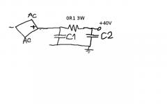
Use the cheaper caps as the raw smoothing caps at the output of the rectifier. The better caps are then separated by a small resistance CRC, the better caps provide a low impedance output to drive the amplifier.
Even without the R, the better caps provide a low impedance source for the amplifier.
Wake me up when you find these inductors for a solid state powerful amplifier.One more advice: I would not only place the better caps near the amps, but (referring again to post 19) i suggest to place XXX µH inductors (instead of resistors) between the rail-poles of the different e-lytic types. Inductors can have very low DC-resistance, though their better filtering action.
Please, think of this idea. Good dimensioned inductors would allow a much more dynamic.
If you decide to follow my advice (i would be glad, if you do ... especially related to "my" inductor advice (smile)
")
Last edited:
I still haven't found a PSU circuit with an inductor as #20 suggested.
Only question remaining is, will it be better than using identical caps without a resistor?
I'm hope I'm not asking here too novice questions, but it's my first high W build...
Thank you, I think I have it, it's Rectifire+ to Cap1 and to 0.1R, 0.1R to Cap 2 and to + output.The better caps are then separated by a small resistance CRC, the better caps provide a low impedance output to drive the amplifier.
Only question remaining is, will it be better than using identical caps without a resistor?
I'm hope I'm not asking here too novice questions, but it's my first high W build...
Last edited:
Attachments
I see. Ripple current sort of includes the thermal resistance, I presume this is assuming free air convection.
I wonder why, as far I know, we do not put heatsinks on the power supplies big caps.
While we are at this, what should be known about the temperature rating of these caps, just a max temp rating ?
I wonder why, as far I know, we do not put heatsinks on the power supplies big caps.
While we are at this, what should be known about the temperature rating of these caps, just a max temp rating ?
40 x 1.41 is 56 volt.
The cap charges at peak voltage minus one diode drop.
Vrms x √2 - Vd
Usually, one takes Vs=0.7 but here, it is smaller because of no load but the cap current leak.
Australia mains is 240V, France is 230V but they keep naming it 220V as it used to be.
Mains voltage is +/- 5%.
40V transformers don't care about these details.
Last edited:
10k is very little load, it makes about no voltage drop and very little ripple, so your DC measurement is ok regardless of actual type of DC measurement.
10 k does some load current easy to calculate.
With known cap value and load current value, one can calculate the ripple peak to peak voltage.
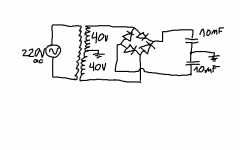
Beware of mF that is milli Farad, uF that is micro Farad.
10 k does some load current easy to calculate.
With known cap value and load current value, one can calculate the ripple peak to peak voltage.
Beware of mF that is milli Farad, uF that is micro Farad.
Last edited:
Thank you so much for your reply.40 x 1.41 is 56 volt.
The cap charges at peak voltage minus one diode drop.
Vrms x √2 - Vd
Usually, one takes Vs=0.7 but here, it is smaller because of no load but the cap current leak.
Australia mains is 240V, France is 230V but they keep naming it 220V as it used to be.
Mains voltage is +/- 5%.
40V transformers don't care about these details.
So let me get this straight, the ac in the secondary should be 43V (since the mains is 236V ac and the trans is rated 220-40), but the dc output of the rectifier measures 62dc. Why does rms comes into play suddenly? This is confusing and frustrating especially because the rating of the amp is in DC and 62Vdc is so close to the required V up to around 58-60V max....
Another issue is what kind of measurement my meter makes in a non pure dc voltage... probably not true rms on the caps.
I also added two 10k resistor for loads and it didn't change the voltages.
- Status
- This old topic is closed. If you want to reopen this topic, contact a moderator using the "Report Post" button.
- Home
- Amplifiers
- Power Supplies
- I have the parts of a PSU kit, but don't have the schematic... which should I build?