The AC voltage is a sine wave and it's voltage is given an rms (root mean squared) valueWhy does rms comes into play suddenly?
Root mean square - Wikipedia
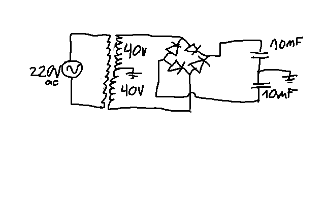
The output voltage of a mains transformer is given by:I put together this little PSU and I get 62V measurement on each of the capacitors - what could be the explanation for this?
Vout= Mains voltage/Rated primary voltage * Rated secondary voltage * (1+ transformer regulation).
eg.
transformer is a dual 230:40Vac 7% regulation and mains is 243Vac
Vout = 243/230*80*(1+0.07) = 90.44Vac
Convert to peak and you have 127.9Vpk.
Subtract two diode drops of 0.5Vf (when near zero current is flowing)
You will have 50% of 127.9 - (0.5+0.5) = 63.45Vdc on each smoothing capacitor.
Find out your supplier's maximum mains voltage. Use that to determine the voltage rating of your main smoothing capacitors.
If your voltmeter is specified as rms reading than it measures the voltage using the rms method and that takes account of the AC waveform and all the other ripples interferences and waveform, distortions that increase the effective power of the basic sinewave....................
Another issue is what kind of measurement my meter makes in a non pure dc voltage... probably not true rms on the caps.
I also added two 10k resistor for loads and it didn't change the voltages.
If it is not rms reading, then it is almost certainly an average reading voltmeter.
It measures the average voltage over a sequence of waveforms and then applies a conversion factor to create a reading that is the equivalent of a sinewave AC waveform.
The averaging and conversion gives a reading that is very close to a sinewave if the distortion (flat topping) is low. This under-reads the POWER that the voltage waveform can transfer to your circuit.
This is why I do not write/type Vrms, when I actually mean Vac for a sinewave.
AC characteristics are almost always RMS, unless otherwise specified.lamir35 said:Why did nobody tell me the ac ratings are rms?!..
See how much voltage it drops under load. You might not need to do anything else.
I just tried it with 700ohm load and the reading was almost identical. I'll try testing it with a 70ohm load.See how much voltage it drops under load. You might not need to do anything else.
Perhaps the main question is, will it still exceed the maximal voltage peak to peak some of the time when the amp is connected to it?
The HD M400 which has no documentation unfortunately and comes with a ready PCB. I don't know the class but uploaded pics of the board if it helps. It's purely dual mono (two PSU's using two transformers), not sure about the Watts but other built is using 2 x transformers, 2 x 35 vac / 300 VA each, to get 100W in 4ohm.What is the amplifier you want to power with this 2 x 40V transformer ?
What is it' s power and Class ? Is it, for instance, a two channel Class B. Like 2 x 100 Watts Class B for 8 ohms loud speakers.
The AC is 40Vrms.Please measure the AC voltages at the secondaries
You measured 40V ac at the secondary.
At each 40V 0 40V secondaries.
About the schematic on post #37 You measured 62V dc at each cap.
There is something wrong.
40V ac is not consistent with 62V dc.
40V ac should give 56V dc. Because:
40 x 1.414 - 0.5 is 56.
There is something wrong in your meter or the way you use it.
Or the schematic is not as shown in post #37.
Compare what you measure on known AC and known DC supplies.
Last edited:
the information is wrong.The HD M400 which has no documentation unfortunately and comes with a ready PCB. I don't know the class but uploaded pics of the board if it helps. It's purely dual mono (two PSU's using two transformers), not sure about the Watts but other built is using 2 x transformers, 2 x 35 vac / 300 VA each, to get 100W in 4ohm...........
A dual 35Vac gets you to about +-50Vdc to +-51Vdc.
That gives a decent amplifier an output of 100W to 110W into 8r0 dummy load.
Expect at least 170W into 4r0 dummy load. A really good amplifier that is not current crippled will get 190W to 200W into 4r0 from a dual 35Vac transformer.
Wake me up when you find these inductors for a solid state powerful amplifier.")
At first: Sorry, i placed one X too much into my post. I meant XXµH, and also staying away from 100µH. Too much inductance would result either in a high-ohmic, or much too big inductor (but maybe in both cases in a too low corner frequency, to give the bass still enough power). Forget about it, declaration later in the text...
"when i find" - oh, i would find them in my own designs. I like to place a high ripple rated e-lytic (plus a little resistance in series - its value depending on current, to reduce the actual ripple) before a low-ohmic power (storage) inductor, followed by the familiar high capacitance.
The effect of an inductor directly after the rectifier would be flattening and broadening the current pulse (and reducing its rms value, giving better power factor). But these inductors would be very huge, if someone wants to get rectified power near the value of the rating of tranny (which is mostly secondary AC, pure resistive load).
The mentioned electrolytic-littleinductor-electrolytic (CLC) normally is only my own choice, and for modern audio amps with their good PSSR not necessary.
I only decided to give this advice, because someone suggested the use of resistors in between the lytics, what is - in my mind - much more pointless for a high current supply, than a right dimensioned inductor would be.
So if you decide to sleep till someone will find - i would let you.
Because i would not have to search for them very long.
/OT end.
Dear lamir, Andrew is right about the voltage/impedance/power relation theme.
Also about your measurements, the suggestions about measurement errors (and/or actual voltage and actual transformation ratio) are right.
But there´s one point more than this:
Almost any power transformer´s voltage rating is meant at rated load. (!)
The idle voltage of transformers can differ very strongly from loaded voltage.
That depends on power rating (thinner wire - current through a higher resistance gives more voltage drop), but also the exact coupling factor (and so the resulting stray inductance [higher at bad coupling], which is in electrically series, and also gives lower voltage at higher loading), and this factor is related to the exact construction of the transformer.
More often than not, toroid transformers are better at this aspect, than others. But if the windings are not distributed roughly equally over the core, even the coupling factor of toroids would suffer a little.
Hence a little "no load overvoltage" is inherent to every real transformer.
And some kiloohms are no "load".
Try much lower values (rated for the power). You could go till 20 Ohms across both the lines, for a short period. If you measure much lower voltage then, the coupling factor would probably be the cause.
But if so, the knowledge is no solution yet. (Because the idling voltage still can destroy your amp - if it´s really that sensitive to that, noone knows...)
Maybe you could add some windings to the primary. That would be a good solution, but is not practically in every case.
And (if someone wants to laugh about again, i don´t care) an alternative (better only temporarily...) way would be to connect a choke (maybe from a big discharge lamp) in series with the transformer primary - although this big choke would be really clumsy...
The choke would give an inductive voltage divider, and the primary voltage would reduce.
Also someone could use calculated/ size optimized chokes at the outer secondaries, but i´m too lazy to calculate now - because the resulting chokes for such a big voltage drop would be really huge, and noone would use (to build and/or buy them, would be costly - and the result would be really heavy, i think), if there´d be another way...
What kind of transformer do you have exactly, what´s its rating, etc.?
Don´t you have a more exact description (or eventually a datasheet) of it?
Sorry, it would be no classical voltage divider. The classical inductive voltage divider would have one core. But there would be a voltage drop at the choke.
Another way (most often possible) would be, to buck the input to the transformer with another one. The other tranny only has to be small, if you have one rated 240V/36V and the secondary equals the rated primary input current (or better more),it would work, especially with a load like an audio amp, which almost never would drive the maximum current.
Bucking Xfmrs
I measured it now and without a load it's 62V dc in caps and 45V ac in secondaries.You measured 40V ac at the secondary.
At each 40V 0 40V secondaries.
About the schematic on post #37 You measured 62V dc at each cap.
There is something wrong.
You are right. I don't know the loss in the amp, but it doesn't matter anyway, since 100W would be enough for a small home amp. The trans is rated to 3.6A, so that's the limiting factor, so 200W is unattainable.the information is wrong.
A dual 35Vac gets you to about +-50Vdc to +-51Vdc.
That gives a decent amplifier an output of 100W to 110W into 8r0 dummy load.
Expect at least 170W into 4r0 dummy load. A really good amplifier that is not current crippled will get 190W to 200W into 4r0 from a dual 35Vac transformer.
I just tried using a 40ohm as a load, on between the V+ rail and 0V ground, and the V in cap dropped only to 60V (in other words the current was divided in half between the two secondaries to 0.75A on average).Almost any power transformer´s voltage rating is meant at rated load. (!)
The idle voltage of transformers can differ very strongly from loaded voltage.
That depends on power rating (thinner wire - current through a higher resistance gives more voltage drop), but also the exact coupling factor (and so the resulting stray inductance [higher at bad coupling], which is in electrically series, and also gives lower voltage at higher loading), and this factor is related to the exact construction of the transformer.
More often than not, toroid transformers are better at this aspect, than others. But if the windings are not distributed roughly equally over the core, even the coupling factor of toroids would suffer a little.
Hence a little "no load overvoltage" is inherent to every real transformer.
And some kiloohms are no "load".
Try much lower values (rated for the power). You could go till 20 Ohms across both the lines, for a short period. If you measure much lower voltage then, the coupling factor would probably be the cause.
But if so, the knowledge is no solution yet. (Because the idling voltage still can destroy your amp - if it´s really that sensitive to that, noone knows...)
...
This isn't low enough assuming it's not far from idle current. Adding the 0.5ohm resistor after the first cap as was suggested before will only drop the V by a meager 1.5V.
I'll have to read up on chokes, thank you for the suggestion.
The transformers are toroidal 300VA, 2x 40V 3.6A, 2x 15V 0.4A . A short googling showed it's not a good idea to try to modify it.
I don't understand. How is adding another transformer a better solution than changing the transformers to new ones?Another way (most often possible) would be, to buck the input to the transformer with another one. The other tranny only has to be small, if you have one rated 240V/36V and the secondary equals the rated primary input current (or better more),it would work, especially with a load like an audio amp, which almost never would drive the maximum current.
Last edited:
A dual 40Vac transformer will give roughly +-56Vdc to +-60Vdc at the smoothing capacitors with a pair of low bias ClassAB amplifier connected and set up...............
You are right. I don't know the loss in the amp, but it doesn't matter anyway, since 100W would be enough for a small home amp. The trans is rated to 3.6A, so that's the limiting factor, so 200W is unattainable.
..................
The transformers are toroidal 300VA, 2x 40V 3.6A, 2x 15V 0.4A . ..............
This will give 150W to 170W into 8ohms, one channel driven. With both channels driven expect 10W to 20W less.
If you have 6ohms loads then you should get 180W to 200W into 6ohms, both channels driven and over 200W into 6ohms, one channel driven.
A 300VA transformer is good for 150W to 300W of total maximum power for domestic duty listening.
I don't see how you arrived at the conclusion
so 200W is unattainable
The 300VA dual 40Vac is suitable for one channel driving 4ohms. Do not try to drive two 4ohms amplifiers.
I don't understand. How is adding another transformer a better solution than changing the transformers to new ones?
If this would make sense, is up to you, and the circumstances.
There are situations and circumstances at this world, which
could rearrange someones mind to find this useful.
You don´t have to do that.
I do not understand why you do not just use the transformer as is.
Usually a power amp doesn't care much about an exact power voltage.
The real issue is too much current because of too low impedance loud speaker, when running at full volume.
Another issue to look at is: The quiescent current must stay reasonnable. An easy check is: With no load, no speaker, the heat sinks temperature should stay acceptable.
I bet you'll be fine with some over voltage, just make sure you do not push volume too high in case of low impedance speakers.
Last edited:
- Status
- This old topic is closed. If you want to reopen this topic, contact a moderator using the "Report Post" button.
- Home
- Amplifiers
- Power Supplies
- I have the parts of a PSU kit, but don't have the schematic... which should I build?