Here is a search i did for 3.3 volt regulators.
positive fixed
3.3v
number of regulators 1
1A to 1.5A
PMIC - Voltage Regulators - Linear | Integrated Circuits (ICs) | DigiKey
If you look in the column "voltage dropout typical" You can see how much voltage over 3.3vdc the regulator needs.
Example 6.3 vac transformer, assume 15% line voltage drop. Calculations for 3.3 vdc out.
6.3vac x .85 = 5.355 vac at low line.
5.355 vac x 1.414 = 7.57 vdc
two diode voltage drops, use Schotty diodes, 2 x .7vdc = 1.4vdc diode drop.
7.57 vdc - 1.4 vdc = 6.17 vdc
You will have ripple on the 6.17 vdc, the ripple will depend on how much capacitor you have. Lets just say .5 vdc.
6.17 vdc - .5 vdc = 5.67 vdc
5.67 vdc - 3.3 vdc = 2.37 vdc for "voltage dropout typical"
So i would say a 6.3 vac transformer would give you plenty of headroom for the regulator.
BTW, do not order anything yet. Let this post sit for a day or two. Others will look and have more ideas or correct any mistake.
Last edited:
BTW, do not order anything yet.
Indeed, that is how I ended up with two trafos instead of the anticipated one for my psu outputs, LOL. Live and learn. Agreed, I will return with more questions and await further assistance, thanks again!
BTW, the 3.3 vdc LDO regulators are made to run off of a 5 vdc supply. So if you are happy with sharing then this would be the way to go.
You could also repeat the calculations above for the 5V output using a 5 v LDO regulator and use a lower voltage transformer for less watts dissipated.
You could also repeat the calculations above for the 5V output using a 5 v LDO regulator and use a lower voltage transformer for less watts dissipated.
Hi Bob, got to look over the mathematical breakdown (which is inclusive and helpful for a newbie, thanks!) and one question came to mind. You have mentioned to use schottky diodes, which I assume is because of their lower Vf which translates into less heat buildup on the diode. Good choice, but why are we using the same v. drop value as standard diodes? Aren't most schottky diodes at a significantly lower v. drop, like .1-.2 volts? Some that I have looked at with If of 1A-1.5A range between 0.3-0.4V. Am I missing something? Thanks again.
I will get back to selection of parts after some careful brainstorming, perhaps late day monday. Stuck working this weekend
I will get back to selection of parts after some careful brainstorming, perhaps late day monday. Stuck working this weekend
I picked .7 because from memory it is worst case for high current schottky's. For regular diodes i would have used 1v.
Ok, cool, thanks. Will chat with you again soon!
Do not forget this is a experimenters power supply. You will have leads all over the place, bare wires, short circuits. Do not be afraid to over spec the diode bridge a lot. I would use at least a 10 amp bridge. For voltage 2x minimum.
Very good points
And fuses on each of the output trafo's primary winding. Maybe a PTC for the digital outputs? Do you think a PTC would be fast enough?
PTC's are very slow and any normal fuse is slow compared to a semiconductor burning out. These devices would only be used to protect your circuit.
Fusing seems simple but can get very complex. Lets think a little about your project. You do not want nuisance tripping but you want to protect your power supply. I would not want to replace a fuse every time your output had a brief short. But you do not want to burn up your power supply.
Lets work out a scenario and see how it plays out. Modern 3 terminal regulators are fairly burn out proof. They have thermal and current shut down circuitry. I did a search for a LM317 and the first one that came up was a TI LM317-N, 40vdc in, 1.5A out. Page 7 has some current specs. 1.5A min, 2.2A Typ, and 3.4A max. We have to use 3.4A worst case x our 1.5 current factor for bridge rectifier = 5.1 amp that the transformer will see. Your transformer from memory was a 20 vac, 56va so 56va/20vac = 2.8A. Transformers are fairly forgiving in the short term and will probably survive this overload for at least as long as a PTC takes to trip without any harm.
I looked up PTC in digikey and found these two.
RHEF100CT-ND, .300 ohms, 1A hold, 1.8A trip.
RHEF100HF-ND, .430 ohms, 1A hold, 1.8A trip.
Digi specs say only difference is the R max. Datasheet says both are the
same.
So if you used this PTC on the secondary and the LM317 was 1.5A min current limit, then this PTC would never trip. Realistically this would never happen unless some thermal factor was factored in here. These 3 terminal regulators do not have a sharp knee of 1.4999 amps ok and 1.5 amp = current limit. So the PTC may work, but looking at the spec sheet, the 5.2 second trip time is for 5.0 amp max and no spec is given for the 1.8A trip. So to know for sure if this would work you would have to buy one and try it.
Or you could just put it in, you will not get a nuisance trip from it but it may not trip when you want it to. Lets check typical values, LM317-N typ was 2.2A, the PTC will trip at 1.8A but we do not know how long it will take. The max LM317-N trip point was 3.4A and again we do not know how long it will take to trip.
So i would say the PTC might save us from a short but it is not guaranteed. The plot thickens here for another reason. You were shooting for 0-20vdc at 1A but you could easily get 0-20vdc at 1.5A because of your 2.8 amp transformers. 1.5 x 1.5A = 2.25A from transformer, plenty to spare.
If you go to 1.5A the 1A hold PTC will be used out of spec and we need to pick out a new one, but i suspect with a smaller hold to trip range we will come up empty. We need 1.5A hold and the min current limit on LM317 is 1.5A, So scientifically speaking no device can work!
But the closest PTC's have this spec.
30v, 1.35A hold, 2.7A trip, .115 to .130 ohms.
Well typical current limit on LM317-N = 2.2A, so this has a chance for some kind of trip on the PTC but we do not know how long, the spec on the one i brought up is 7.3 seconds at 6.75A and as before we know we will never see more than LM317-N max current of 3.4A. Once again you would have to try it and see.
To sum things up i do not see a good answer for the PTC where the numbers work out. I think you could use a PTC for long term overload though.
We still have not talked about primary fuses and how those fit in the various scenario. This is why i said at the start, fusing can get very
complicated.
I will make a fuse post in my next post.
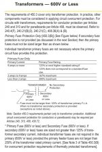
See pdf, the first paragraph on the first page shows transformer fusing codes. ($%^& file to large, i sent jpg instead).
You have a 56va transformer with a 2.8A secondary so code says fuse for primary must be 167% maximum. 56va / 120vac = .467A, or look up mfg spec for pri current.
.467A x 1.67 = .779A
Closest digikey fuse without exceeding .779A is .750A
My selections.
voltage rating AC 120/250.
.750A
Mounting type holder.
I do not see any mention of time delay fuses being a problem in the pdf so select slow blow. This leaves only 13 choices, match a fuse with a fuse holder you want to use.
Each transformer should have it's own fuse. Notice in the fuse code chart that small transformers can have up to 300% maximum current. This is for inrush to prevent nuisance tripping. Your small transformers will use this spec.
These are the maximum fuses you are supposed to use by code. If you have nuisance tripping from say a huge capacitor on the secondary and lots of inrush, code says that is your problem! You may not increase the fuse size. You would have to limit inrush by adding resistance on the secondary. So do not go hog wild with lots of capacitance. I think the author did a good job with using 4700uF caps for 1A out, only slightly overkill. For 1.5A 4700 to 6800uF will be enough.
I selected
capacitors aluminum
4700 to 6800uF
lifetime temp, all 105 deg and not 1000 hour.
35vdc
thru hole
53 choices were left any of them will work. My two favorites were.
565-3931-ND, 4700uF 35vdc, 10,000 hr, 4.22A ripple, $2.68
565-3932-ND, 5600uF 35vdc, 10,000 hr, 4.28A ripple, $2.59
I was going to do a primary current check but i can not. If you go with LM317-N max current limit of 3.4A worst case x our 1.5 current factor for bridge rectifier = 5.1 amp that the transformer will see. But this is as far as we can go. The voltage will drop at 5.1A so we no longer have 20 vac out so we can not easily work back words to the primary current.
So bottom line is, we have to live with the primary fuse values and if there is a problem with nuisance tripping we have to fix it in the secondary. Of coarse if you want your primary fuse to blow on a current limit you can use a lower value.
Attachments
OK, big surprise. I did not know you could not buy a schottky bridge rectifier unless it is a special order, you have to build it with individual diodes.
In regular bridge rectifiers there is a good assortment from 6A to 20A and 50 to 100 peak reverse volts, thru hole, various mounting styles. Pick one that will work out with your heat sink scheme.
If you build a bridge rectifier with schottky diodes remember that each diode only see's half the current. But i would still go for diodes from 5A to 10A at 50 to 100vdc. The higher current diodes will have more surface area to aid cooling.
Just thought of something, you can fix nuisance surge current tripping on the primary side with "inrush Current Limiters (ICL)". Digikey is down right now so i can not look one up.
This is an example of one i used recently, slightly smaller than you need.
317-1153-ND
22 ohm 600ma 1.108 ohm at current.
You could also add a MOV and X2 capacitor for spike protection. The MOV must be placed after the fuse because it fails shorted. The capacitor should also go after the fuse for safety reasons.
My favorite MOV for 120 vac circuits. This goes across the 120vac line, line to neutral.
MOV
320vac max
12ka
495-4296-ND
$1.44
X2 capacitor anything from .33 to .56uF general rule, this goes across the 120vac line, line to neutral.
399-5869-ND
.47uF
310vac
66 cents
BTW, do not let me talk you in to something you do not want to do. It is easy for me to say make the supply 1.5A instead of 1A but you have to live with the thermal factor.
Ball park numbers.
20vac x 1.414 = 28vdc - diode drop = 26vdc from your raw power supply.
You adjust power supply to 5vdc.
26vdc - 5vdc = 21vdc the regulator must drop at 1.5A
P=IxE, 1.5 x 21vdc = 31.5 watts your heat sink has to dissipate.
21vdc at 1A
P=IxE, 1 x 21vdc = 21 watts your heat sink has to dissipate.
Thermal calculations will be very important.
If you look in the column "voltage dropout typical" You can see how much voltage over 3.3vdc the regulator needs.
Example 6.3 vac transformer, assume 15% line voltage drop. Calculations for 3.3 vdc out.
6.3vac x .85 = 5.355 vac at low line.
5.355 vac x 1.414 = 7.57 vdc
two diode voltage drops, use Schotty diodes, 2 x .7vdc = 1.4vdc diode drop.
7.57 vdc - 1.4 vdc = 6.17 vdc
You will have ripple on the 6.17 vdc, the ripple will depend on how much capacitor you have. Lets just say .5 vdc.
6.17 vdc - .5 vdc = 5.67 vdc
5.67 vdc - 3.3 vdc = 2.37 vdc for "voltage dropout typical"
So i would say a 6.3 vac transformer would give you plenty of headroom for the regulator.
Hi Bob, I have read through the PTC and fuse discussion and there is certainly much there to talk about, but I want to bring the focus back to the 'digital' outputs for some questions that I have.
The above calculations would satisfy the 3.3v LDO based output, but there would not be enough headroom for a 5v LDO. Case in point, the LM1086 5 would need a max of 1.5v Vdo which would drop the input to 4.1vdc.
The next xfmr I found is at 8v in parallel which would give more headroom for the 5v channel, but the rest would be waste heat for the 3.3v channel.
Here are my calculations:
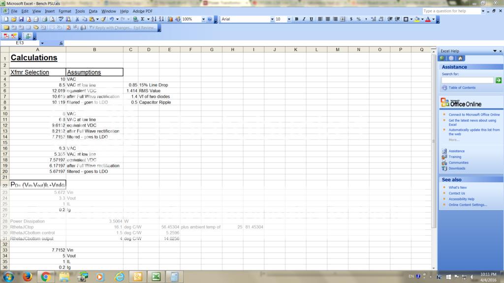
The 8v xfrm would yield about 90deg C at max load for the 3.3 channel.
I am trying to get both channels out of one transformer due to space constraints.
As for heatsinking, I liked the authors method of attaching the regulator to the body of the case - large thermal mass!
Looks like a misunderstanding here. I was just taking a guess at a transformer voltage and going through the calculations so you could see how it was done. On that 6.3vac transformer i was thinking separate transformer for 3.3vdc. I expected you to pick your own transformer for the regulator you want to use.
Also for the 3.3vdc supply you would feed the 3.3vdc regulator from the 5vdc output. That is why the LDO regulators were invented.
Also for the 3.3vdc supply you would feed the 3.3vdc regulator from the 5vdc output. That is why the LDO regulators were invented.
<<Also for the 3.3vdc supply you would feed the 3.3vdc regulator from the 5vdc output. That is why the LDO regulators were invented.>>
Interesting, so what you are saying is that one would first regulate down to the 5vdc output and then from there regulate with another LDO to the 3.3v output. Thus the second LDO doesn't have to work so hard.
If I have that correct, then it would mean that I would need a xfmr capable of 3A (1A per channel x 1.5 multiple) at about 8VAC. The first step down would be to 5v, take the output and tap that to make one of the 5v digital outputs and the other connection would go to the next LDO for the 3.3. This means that there would be at least 2A+ going through the first LDO.
Here is a xfmr that I thought might do the trick if the above is on the mark.
Here is a LDO that is rated at 3A.
Am I going down the correct path now?
Thanks!
Umm, i thought you said you would only use one of the low voltage outputs at a time. But even so, if you used them both, it is hard to believe you would use both at full power at the same time. However for the few extra dollars you can have full power on both. So yes i agree with your calculations.
The transformer you picked is fine. The regulator at 3.3vdc 3A seems to much if you want to run it off of a 5vdc 1A regulator. The 3.3v regulator would never go into current limit but the 5v one would if you drew to much power from the 3A. It does not help to oversize a linear regulator.
The transformer you picked is fine. The regulator at 3.3vdc 3A seems to much if you want to run it off of a 5vdc 1A regulator. The 3.3v regulator would never go into current limit but the 5v one would if you drew to much power from the 3A. It does not help to oversize a linear regulator.
I am rethinking running 3.3 and 5vdc off of the same transformer. This is done all the time on the PCB but on the PCB the designer has full control of the ground point and were they join. Your ground point will be at the power supply and have to run through all of the power cables. Modern high speed and mixed signal electronics will have a problem with this.
- Status
- This old topic is closed. If you want to reopen this topic, contact a moderator using the "Report Post" button.
- Home
- Amplifiers
- Power Supplies
- Bench Power Supply