I am using these for voltage and current displays for a power supply I am working on.
Mini DC 0 100V RED LED 3 Digital Display Voltage Voltmeter Panel Motor | eBay
Mini DC 0 100V RED LED 3 Digital Display Voltage Voltmeter Panel Motor | eBay
Thanks Andrew! I understand what you are using the LED for. I was just using mine for a general 'on' indicator, but I can see how what you have done is far more useful, thanks!!
Hi multisync, do you have a post on your supply that I can look at? Here is the meter that I am working with, I had some on hand.
Hi multisync, do you have a post on your supply that I can look at? Here is the meter that I am working with, I had some on hand.
The power supply that I am working can be found here.
0-30 VDC Stabilized Power Supply with Current Control 0.002-3 A - Electronics-Lab
I found boards and parts for it on eBay for less than $20. I am changing it slightly so the ps can supply minimum 5 amps at 30 volts and max current is either 500ma or 5 amps.I tested it at 6 amps into a 2 ohm load and the current limit works well.
I saw those meters also but I didn't see the connections for current and voltage. I needed different reference points for current and voltage.
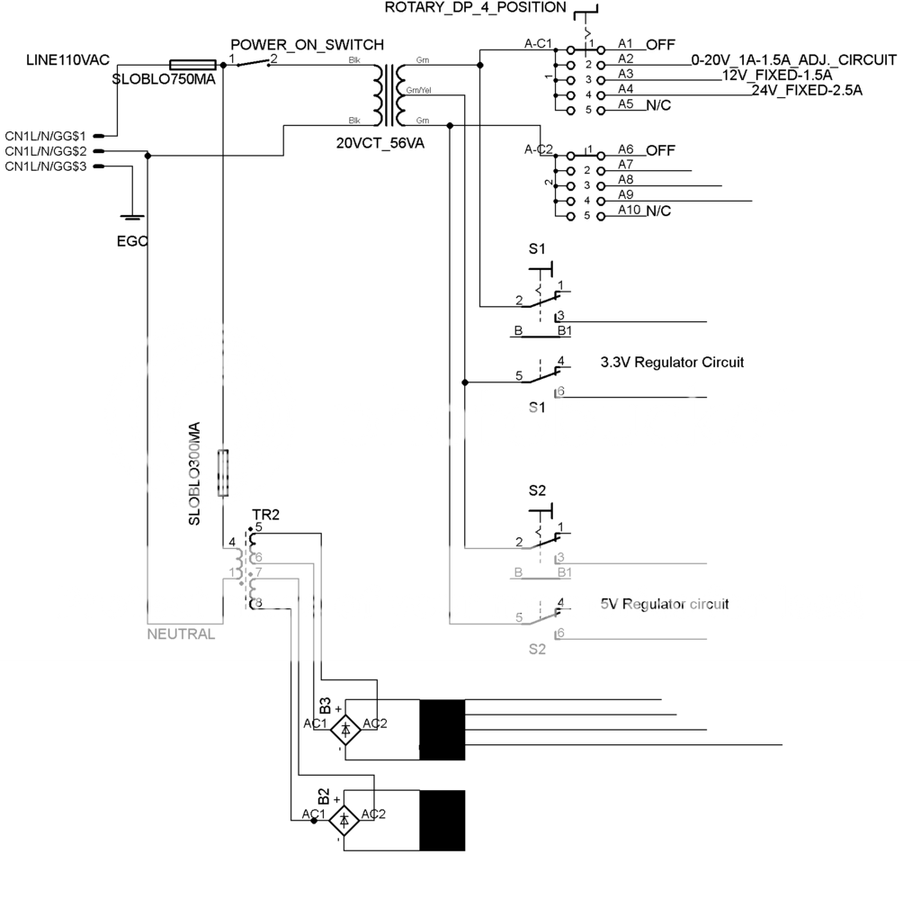
After some thought, I think that I have gotten powerbob's excellent suggestions into a usable form. I do need to have a one case design, as small as possible. The schematic above is partial - I really just wanted to ask a few questions about the approach. I thought it would be really cool to access the various 'voltage supply circuits' via a multiposition rotary switch. I figured out how to do that for the circuits that use the outer windings. For the two lower voltages that will use the center tap, they each went on their own DPST switches. As is, it looks like I can use either 3.3v or 5v individually or at the same time.
- Should the bridge and cap. bank be ahead of the rotary switch to minimize components? i.e. cap/bridge common to all three upper circuits with separate regulators and discretes?
- Should the rotary switch be 'make before break' to prevent arc damage on the contacts?
- As drawn, if the center tap fed circuits are in use, would I still be able to have 20VAC and be able to use the upper circuits (albeit at a reduced current)?
I really like this approach, more flexibility, a few more parts and regulators, but very interesting! If this is a possibility, I would replicate the same group of circuits for the second transformer. The xfmr on the bottom is for the panel meters. To save space and number of panel meters, the upper three circuits switched by the rotary switch would share one panel meter - I assume that I would simply need to common their outputs - I haven't fully elaborated on this yet and I am hopefully that this will not be a problem.
Your thoughts?
Let me think about this out loud.
You really need separate power supply's, that you can use at the same time.
Example you will have a 5vdc powering a micro and a 12vdc powering relays and sensors.
A power supply that will give you 3.3vdc or 5vdc or 12vdc or 24vdc will be of limited use. But if you have two of them that would help as it is fairly common to need two supplies. You would still need a separate +-15vdc supply.
So while this could be made to work on paper, in actual practice you could no longer parallel the two high power supplies because you would loose your ability for having the low voltage logic power supplies available.
You seem to have your heart set on one big power supply box. As a practical matter separate boxes for some of these supply's will be easier to use. The two 56va supply's should be separate from all others. They could be used to power inductive loads like motors, solenoids, big relays, with large inductive spikes and noise. You want these supply's on the other side of your work bench from your logic supply's.
with large inductive spikes and noise. You want these supply's on the other side of your work bench from your logic supply's.
Thank you Bob!! That is an excellent observation. I will

and return!
Someone considered using this PSU ?
DIYfan: Adjustable Lab Power Supply - take two")
I built it on veroboards, two channels in one case forming +/-30V split supply's if necessary. 2.5 years has been passed and it is still in use all day long, it eats everything and protects it at the same time. It is really variable from every corner.
Decided to use it in audio circuits with 50V DC transformers, so i made PCB. If tested and ok, i will publish the PCB's
Please, All credits to the Owner of that linked blog.
DIYfan: Adjustable Lab Power Supply - take two
I built it on veroboards, two channels in one case forming +/-30V split supply's if necessary. 2.5 years has been passed and it is still in use all day long
, it eats everything and protects it at the same time. It is really variable from every corner.Decided to use it in audio circuits with 50V DC transformers, so i made PCB. If tested and ok, i will publish the PCB's
Please, All credits to the Owner of that linked blog.
Attachments
Last edited:
Hi rensli, thank you for posting. I have seen that design before on electronics_labs. I like that you have had long term success with it! I am still debating whether I will use the 317 or not. I probably will since its the easiest to work with.
I am also still digesting what bob and andrew have been telling me. Especially that an all in one solution is not the best choice with digital circuits! I thought it would be cool to have everything in a compact package, but as bob mentioned, the circuits that have relays, motors, etc. would have an abrupt collapsing magnetic field inducing a spike. That would cause havoc with the digital signals.
I am currently looking at using my two 20vac, 56va xfrms as a twin channel 0-20ish vdc 2.5A supply and then separately as bob suggested a 12,24vdc supply. The 15vdc I will forego or just get from the 20vac supplies when needed. The 12/24 supply I am thinking about getting from two xfmr with 24vct.
The digital section I will most likely put into a separate box and I will delay doing that until I finish this other psu first.
- Status
- This old topic is closed. If you want to reopen this topic, contact a moderator using the "Report Post" button.
- Home
- Amplifiers
- Power Supplies
- Bench Power Supply