? Are you sure?..................
If you build a bridge rectifier with schottky diodes remember that each diode only see's half the current. But i would still go for diodes from 5A to 10A at 50 to 100vdc. The higher current diodes will have more surface area to aid cooling.
A bridge rectifier passes the current through two diodes, effectively in series, on alternate half cycles of the supply.
That equates to each diode passing the current with a duty cycle of 50%. That is not the same as passing half the current.
The heating in a diode is I * Vf at any instantaneous moment.
If the duty cycle is 50%, then the average total heat load is halved.
I thought you compared the schottky to the traditional.
Where the schottky only drops roughly half the voltage.
As the pdf and AndrewT also sad the diode sees the full 6A, just at 50% time.
From heat point of view it is the same, but from stress point of view it is not the same.
And the doc also states to use at least double the amp rating. So for 6A trafo at least 12A diode.
Umm, i thought you said you would only use one of the low voltage outputs at a time.
Hi Bob, when we talked about not using them together, it was in the sense that they would not be series'd together as in making 8.3v total. That came from the discussion of the author's intention to have everything isolated and floating from each other. The 3.3 and the 5v outputs could be used simultaneously in a microcontroller project that used different families. The regulator I listed in post #36 was a 5v LDO rated at 3A (1.5 x the expected total load of the 3.3 and 5v outs). The next LDO which I have not selected would be rated at 1.5A and 3.3v, that would regulate off of the first LDO. I hope that clears up any confusion.
Agreed, since I have not stated my intentions other than to say I wanted to develop the aforementioned authors dual supply PSU with 3.3 and 5vdc outs using digital panel meters, I will say that I am a novice enthusiast interested at the moment in mostly microcontroller experiments using PIC chips. I am interested in learning more about op-amps and using them in projects. More than that, I don't know what I don't know! I have grown tired of using CR2032's for my experimentation and using wall warts has its limitations.This might be a good time for a grocery list of all the things you might want to experiment with.
I follow what your getting at - induction from the AC lines throughout the house interfering with digital 1/0's. I do intend on having a ground jack beside each output. Would coupling the negative supply and ground not function properly?Basically i am saying a ground loop problem.
For the ground loop, this is what i was getting at. As a typical rule you only join different grounds at one place, such as analog and digital grounds.
You will construct some kind of proto board with both analog and digital components, at some point on that board away from as much digital noise as possible and close to your sensitive analog circuits you will connect those grounds at one point.
You power supply's are an arms length away powering your board with long wires. Because of the inductance of the wires your output capacitors loose there effectiveness. So were your power connects to your proto board you add "bypass" capacitors. These capacitors make the power supply look like it is right on your proto board. However your power supply grounds are already tied together back at your regulators and now when you connect your grounds together on your proto board you have two different paths that ground can take.
As a general rule if you power supply output caps are more than 6 inches away from your circuitry you need to add bypass caps closer to your components. The values would be dependent on current consumption, but for low power stuff maybe a 20uF and a .1uF cap across each power supply on the proto board.
Here is my idea of a good power supply assortment. With the transformers you already have in mind.
All power supply's fully isolated from each other, no common ground.
5vdc 2.5 to 3A. If you get into single board computers like the Raspberry pie you will need 2A minimum for there new ver 3.
3.3vdc anything from .5 to 1A.
12vdc .75A to 1.5A , very popular voltage. Do you want to control real world stuff, relays, sensors, motors, etc.
+-15vdc from 200mA to 500mA for op amp circuits.
0-20vdc 1A, just one of these supply's goes a long way. There may be times when you need two of them but it will be once every few years.
You have two 20vac 2.8A transformers 56va. I would use them to there full potential. Make two separate power supply's, simple unregulated. Bridge, bulk capacitor 10,000 to 12,000uF and a .1uF across that. You now have roughly a 24vdc power supply of decent power for experimenting with audio amps. Some audio power stuff can be powered with a single supply and some needs two supply's for +-. Now you can do both.
You can do another trick, your transformer has spade terminals. If you make connections with push on terminals or use a switch then you could change one of the transformer connections to the center tap now you would have 10vac at 2.8 amp 28va and about 12vdc. You can put this in series with the 24vdc supply for 36vdc or mix and match as you want or parallel the supply's for more power. Maybe you want to control a larger DC motor.
I would break the power supply's up in to separate boxes just to keep the room needed down but that is just an opinion.
3.3, 5, 12vdc in one box. Most useful used everyday.
+-15vdc, separate box. Not used that often.
0-20vdc, separate box. Not used that often.
Two 24vdc power supply's. Could be the same box. Not used to often.
So despite there being two potential paths to ground, so long as there is a decoupling capacitor on the protoboards, we are ok? Or does something else need to be done?However your power supply grounds are already tied together back at your regulators and now when you connect your grounds together on your proto board you have two different paths that ground can take.
All power supply's fully isolated from each other, no common ground.
5vdc 2.5 to 3A. If you get into single board computers like the Raspberry pie you will need 2A minimum for there new ver 3.
Hadn't even thought about that one! I have heard of them, but have not experimented with any.
What would be the advantage in my case for the 5v and 3v to be floating vs. saving the cost and space of getting one xfmr? I could just upsize the xfmr and still be able to achieve the capacity of future R.P. use.
Thanks!
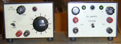
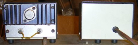
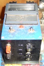
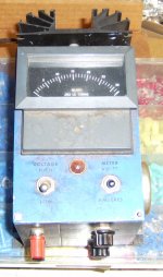
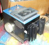
Here are some pics of power supply's i have made. Mostly with surplus components when transformers were plentiful and cheap.
Attachments
"So despite there being two potential paths to ground, so long as there is a decoupling capacitor on the protoboards, we are ok? Or does something else need to be done?"
There is always the possibility of a problem with the 3.3 and 5vdc supply sharing a common ground at the power supply.
You could do another trick. Use the same transformer for both supply's, but use a separate secondary for the 3.3 and 5v. The 3.3 volt supply would have to dissipate more heat but with a .5 to .75A 3.3vdc supply you could save some watts.
Now you have to make sure each secondary winding has enough power for each regulator. I would feel much better with this approach than common grounds.
Those are pretty nice units from salvage parts, Bob!!
<<Use the same transformer for both supply's, but use a separate secondary for the 3.3 and 5v.>>
We were at this point before and the problem I was having here was finding a xfmr to meet the needs of both without producing too much heat in the LDO. Especially now that we definitely want to have 3A's of power at 5v (LOL), it might be harder to find a reasonable priced unit. Off I go to do some hunting on digikey. If I can not find a xfmr with secondary, I will price out two separate xfmrs and see if space wont become an issue. Incidentally, a buddy mentioned that I should put panel meters on both the 3 and 5v out. I mentioned that they were fixed and really shouldn't need to monitor them and he politely reminded me of the time where I was having trouble with an op-amp and couldn't figure out why it wasn't operating as expected
Again thank you for your input and guidance!
Meters are a good thing but you can see how this stuff snowballs in price and complexity. I keep a DVM handy when i am prototyping and when i have trouble i always check the power supply first.
The cutouts for the meters is not such an easy task either. As i said lots of options.
The cutouts for the meters is not such an easy task either. As i said lots of options.
I hope you are still following Bob!
After some searching I found this xfmr - F16-2250-C2.
Dual secondaries at 8v and 2.25A each. I did not find two xfmr's to be economical and space savings are important. My thought at this point is to use a selector switch to parallel the two windings together when I want to have 5v at 4.5A. This switch would have to take the 3.3v circuitry out of the loop while this is taking place. I don't thin that should pose a problem and it seems like a decent compromise.
What are your thoughts?
- Status
- This old topic is closed. If you want to reopen this topic, contact a moderator using the "Report Post" button.
- Home
- Amplifiers
- Power Supplies
- Bench Power Supply