Is this better?
What is the output impedance at 1k, 10k ans 20k?
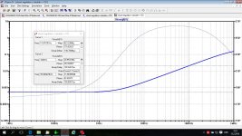
Raise the y-axis so that the curve doesn't cling to the 0 line so that one can see whats going on in the audible range.
Phase shift would be nice within 5 deg 20-20k.
I mean while at it....
Do a statement - end a chapter....
//
I would prefer one with 0,005 ohm as a straight line between 1-50khz as compared with the one you showed. Why, because it would have the same signature impact on the amplifying stages that it feeds. Same goes for phase.
Bit no, I'm not satisfyed with 1 ohm - it's not that easy") so no resistor on the output. The phase criteria would spot it anyway
so no resistor on the output. The phase criteria would spot it anyway
//
Bit no, I'm not satisfyed with 1 ohm - it's not that easy
so no resistor on the output. The phase criteria would spot it anyway //
I would prefer one with 0,005 ohm as a straight line between 1-50khz as compared with the one you showed. Why, because it would have the same signature impact on the amplifying stages that it feeds. Same goes for phase.
Bit no, I'm not satisfyed with 1 ohm - it's not that easy
//
There is no perfect regulator. Have you seen the plot presented by Mark Johnson?
What you mean with 1 ohm?
edit. do you have practical experience with signature impact if a regulator output impedance increases from 0.5 mohm at 20 Hz to 20 mohm at 100 kHz??
Last edited:
Closed loop output impedance is simply open loop output impedance, divided by gain. Unfortunately gain falls as frequency rises, following the well known Gain Band Width product tradeoff.
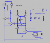
This shunt regulator circuit's output is a MOSFET source follower operating at about 100mA. Its output resistance is (1/gm) and, at 100 mA of drain current, gm is about 1 siemens. The open loop output impedance is therefore about 1 ohm.
If closed loop output impedance must be 5 milliohms or less, the required gain is 200X or more. {Math: 1 ohm / 0.005 ohms = 200X} If closed loop output impedance must remain 5 milliohms over all frequencies from DC to 50 kHz, required gain-bandwidth product is 10 megahertz or more. {Math: 200 x 50,000 = 1e7} 10 MHz GBW product is just barely achievable, but will require much more carefully tuned gate stoppers, carefully selected load impedances, bias points chosen to maximize fT, and optimized frequency compensation. You can get moderately close with LTSPICE. And then you'll need to tweak the real hardware during measurements.
Especially for the positive voltage regulator, where the follower is either Pchannel MOS or else PNP bipolar, I recommend you give careful consideration to selecting the bipolar. It's going to have MUCH higher gm and therefore MUCH lower open loop output impedance. This means you will need a much lower Gain Band Width product in the rest of your regulator circuitry. Use a 2SA1930 or a 2SA2222 PNP on a heatsink, and enjoy your wider zone of constant output impedance.
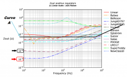
I have superimposed this preference upon John Walton's graphs, below. It is Curve A. Only two or three of the regulators in that test, had sufficiently large GBW product to give 0.005 ohms at 50 kHz. The one labeled "POOGE" is exactly what you prefer, except better (lower impedance), at all frequencies.I would prefer one with 0,005 ohm as a straight line between 1-50khz
Attachments
Last edited:
Thanks for the reply. I have adopted the comfort of sitting in the requirement defining chair. I have full respect for the challenge. I can not design such a source myself. I just want to point this out.
Mark, where there also phase graphs following those impedance plots?
//
Mark, where there also phase graphs following those impedance plots?
//
Build a POOGE and see how you like it. John Walton's listening panel had some very interesting things to say about the sound of the POOGE versus the sound of the Jung_SuperReg_with_AD797. It's in Linear Audio volume 4 (link)
The figures are printed in greyscale in the hardcopy journal, but they are available in color on the Downloads page of Linear Audio's website. Scroll down to "Color Graphs for Walton's Regulator Article in vol. 4" . Maybe the data you seek is among them. If not you could of course construct a useful approximation by making the not-ridiculous assumption of a single dominant pole. Just like we did in Circuits-II at uni. Many of the performance graphs on that plot are clearly and obviously single pole responses; the real world does behave like the theoretical equations, occasionally. That's reassuring. Then adjust the single pole model so it fits the magnitude response in the plot. Presto, this model outputs a not-ridiculous estimate of the phase response too.
The figures are printed in greyscale in the hardcopy journal, but they are available in color on the Downloads page of Linear Audio's website. Scroll down to "Color Graphs for Walton's Regulator Article in vol. 4" . Maybe the data you seek is among them. If not you could of course construct a useful approximation by making the not-ridiculous assumption of a single dominant pole. Just like we did in Circuits-II at uni. Many of the performance graphs on that plot are clearly and obviously single pole responses; the real world does behave like the theoretical equations, occasionally. That's reassuring. Then adjust the single pole model so it fits the magnitude response in the plot. Presto, this model outputs a not-ridiculous estimate of the phase response too.
Last edited:
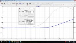
I spent a couple hours this morning, fiddling with modifications to dadod's positive shunt voltage regulator in post #1. I changed to a PNP emitter follower instead of a Pchannel MOSFET source follower, and fiddled with the error amp to get a different point on the gain - bandwidth tradeoff. The result is below. It shows that constant output impedance (both magnitude and phase) over a very wide range, is possible Whether this kind of extreme flatness is desirable, is perhaps another question.
_
_
Attachments
I spent a couple hours this morning, fiddling with modifications to dadod's positive shunt voltage regulator in post #1. I changed to a PNP emitter follower instead of a Pchannel MOSFET source follower, and fiddled with the error amp to get a different point on the gain - bandwidth tradeoff. The result is below. It shows that constant output impedance (both magnitude and phase) over a very wide range, is possible Whether this kind of extreme flatness is desirable, is perhaps another question.
_
Thank you for your effort. This is completely different regulator, mine is symmetric with one trimmer for both polarity and by the way, maybe not so flat but with lower output impedance, and much simpler.
Sorry I don't want to go whos one is ..
Last edited:
Yes there does appear to be an extra cost associated with making the output impedance constant and flat for a wide range of frequencies.
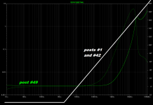
I attempted to overlay the two plots, see below. Although I was careful to choose "good" breakpoints for the piecewise linear approximation, I might have made a mistake. Check it against the graph in #42 to see for yourself.
The white curve is lower impedance at low frequencies, and the green one is lower impedance at high frequencies. Each has a region in which it is "the winner."
Attachments
Looking nice Mark. dadod, yours has a pole in what is the most delicate part of the audible range... It's not like I know that this is bad but to me its "unfortunate" and something I would like to avoid if possible. Why would it be good with extreme performance in one part of the range and just average in an other I don't get the logic in. "The cars turns really good to left but is just average going right" - is this an F1 car?. I mean the impedance is so low that it is almost impossible to carry over to the load anyway - however phase shift will carry through. This is my reasoning.
//
//
Looking nice Mark. dadod, yours has a pole in what is the most delicate part of the audible range... It's not like I know that this is bad but to me its "unfortunate" and something I would like to avoid if possible. Why would it be good with extreme performance in one part of the range and just average in an other I don't get the logic in. "The cars turns really good to left but is just average going right" - is this an F1 car?. I mean the impedance is so low that it is almost impossible to carry over to the load anyway - however phase shift will carry through. This is my reasoning.
//
Why do you think that you can hear difference in output impedance between 0.5 mohm at 20 Hz and 20 mohm at 100kHz it's mystery to me?
Have a look at John Walton's listening panel results in Linear Audio volume 4. The listeners heard a huge difference in subjective audio quality between JungAD797 (low Zout at 10Hz, impedance rise begins at low frequencies) and POOGE (medium Zout, flat across all frequencies, begins to rise at ~90 kHz). The Zout curves are plotted in post #40 of this thread. In the listening tests, music was played thru an all-FET linestage (designed by Erno Borberly), powered by the various different power supplies under test.
Walton also reports the correlation coefficients between listening panel results and various different measured specifications. A delightful read and worth the money IMHO.
Walton also reports the correlation coefficients between listening panel results and various different measured specifications. A delightful read and worth the money IMHO.
Have a look at John Walton's listening panel results in Linear Audio volume 4. The listeners heard a huge difference in subjective audio quality between JungAD797 (low Zout at 10Hz, impedance rise begins at low frequencies) and POOGE (medium Zout, flat across all frequencies, begins to rise at ~90 kHz). The Zout curves are plotted in post #40 of this thread. In the listening tests, music was played thru an all-FET linestage (designed by Erno Borberly), powered by the various different power supplies under test.
Walton also reports the correlation coefficients between listening panel results and various different measured specifications. A delightful read and worth the money IMHO.
I am not sure if both of those regulators are of the same type, could be that the difference is series verso shunt regulator?
The accepted KPIs for a power source "service" seem to be:
- Output impedance
- Noise
- Phase
- Line regulation
- Step response
- more?
as a function of frequency and load. NB: Also, load may itself vary with frequency and in terms of complexity (L, C) of load.
I don't think the load can now what kind of circuit topology the source uses to produce a power feed with a certain set of KPIs form the list above.
//
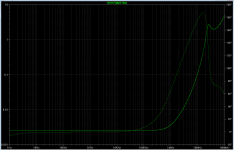
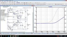
Thanks to discussion, here is improvement, and quite simple. I increased CCS current for mosfet drivers to max 10 mA(it was 3 mA) and output impedance looks much better. Now jfet for CCS should have Idss about 10 mA, and in this case the drivers can drive better mosfets input capacitance.
Attachments
That "looks" much better.
Whether it sounds better is a very different analysis.
I like to see low output impedance and low phase out to beyond 100kHz.
This is where many amplifiers/opamps show poor performance. I consider this frequency region to be important to the system performance.
Post 51 shows two very different philosophies.
Ultra low impedance at low frequency vs low impedance and low phase @ 100kHz.
It would take a lot of research to identify which amplifiers suited which supplies.
Last edited:
I like to see low output impedance and low phase out to beyond 100kHz.
This is where many amplifiers/opamps show poor performance. I consider this frequency region to be important to the system performance.
Agree wholeheartedly, this is paramount to making sure the PSU doesn't add its own signature.
- Home
- Amplifiers
- Power Supplies
- Shunt regulator +-15V