The diyAudio member who gives LTSPICE tutorials is "Mooly", check his posting history to find the appropriate threads. (this one might be a possibility)
I bet he recommends that the first thing you do is VIEW -> SPICE_ERROR_LOG . This is how you find out that your simulation calls for a "DN2540" MOSFET but your model library doesn't have any simulation parameters for DN2540.
Next I think you may want to check whether you've installed M1 backwards.
Next I imagine you'll want to run a .DC analysis or a .OP analysis and compare your voltages and currents against the right answers shown below.
_
Would you, please, open new thread if you want to discuss your regulator.

Member dadod is right; this thread is for his regulator. If DIYA members SSassen or ammel68 created a new thread with the title "Help! I can't get this shunt-mode voltage regulator to simulate in LTSPICE!" it would cut down on the cross pollution here.
Another fine idea might be for those who care the most deeply and feel the most strongly, to launch a second new thread "A voltage regulator's output impedance should be constant from 10Hz to 50kHz, both magnitude AND phase". This would reduce pollution here even further.
Another fine idea might be for those who care the most deeply and feel the most strongly, to launch a second new thread "A voltage regulator's output impedance should be constant from 10Hz to 50kHz, both magnitude AND phase". This would reduce pollution here even further.
Member dadod is right; this thread is for his regulator. If DIYA members SSassen or ammel68 created a new thread with the title "Help! I can't get this shunt-mode voltage regulator to simulate in LTSPICE!" it would cut down on the cross pollution here.
Another fine idea might be for those who care the most deeply and feel the most strongly, to launch a second new thread "A voltage regulator's output impedance should be constant from 10Hz to 50kHz, both magnitude AND phase". This would reduce pollution here even further.
@Mark,
Frankly, unless you intend to rub people the wrong way you can do without the condescending tone in your reply.
Please consider this: you posted a quick schematic and a plot, stating the two belong together. Some people, myself included, took some time out of their busy schedules to actually simulate it and didn't see the results you have posted, or rather, can't seem to get the same plot out of it.
I poked and prodded it left and right and it didn't seem to work. Since I'm not about to spend hours on it I figured I ping you real quick to get some pointers, that's the quickest way to get it up and running I figured.
But rather than providing feedback, or simply uploading your .asc and any .lib you created you point us towards a 'How to start using LTspice' topic? Really Mark, really?
Why not? Why have a variation within the audible range? Just that. Full in.
//
Well that 'why not' doesn't seem to me a good reason to increase cost a factor of 10 or more with no audible difference.
Why not till 1MHz for 50x the price. Or 10MHz for 100 times the price. Full in. Why not?
YMMV.
Jan
@Mark,
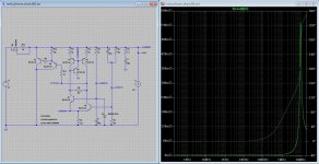
I took another look at your draft and the DN2540 depletion mode MOSFET is key here, I previously picked a NMOS from the LTspice library that seemed suitable and that clearly didn't work. The supertex.lib is essential here, as that has the correct data for the DN2540.
I'm going to leave the .asc and .lib here for anyone else that's interested. For the supertex.lib, the .txt needs to be removed as the forum doesn't allow uploading files with a .lib extension.
Attachments
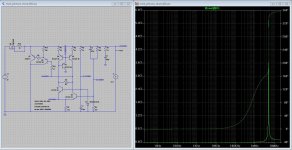
In a shunt regulator like dadod's here, the current source supplies a fixed and constant current. Some of it flows through the load, and all the rest is absorbed by the final shunt transistor. In dadod's post #1 schematic, the final shunt transistors are M4 and M2. He uses an IRF9640 in this position, which is rated for a maximum of 125 watts. Post #49 proposes to use a bipolar transistor 2SA2222 for the final shunt; it is rated for a maximum of 25 watts. Post #70 also proposes to use a bipolar transistor but the text in the attachment is very small, I think it says MJE15031, but I might be mistaken. The 15031 device is rated for 50 watts maximum. Walt Jung's shunt super regulator (link to .pdf) uses a D45H11 bipolar transistor, rated for 60 watts maximum, as the shunt transistor.
Regrettably, post #86 uses a BC327 as the shunt transistor; this device is rated for only 0.625 watts. Since its quiescent point in normal operation is 70mA @ 15V -- which is 1.05 watts -- the transistor Q7 will quickly overheat and fail, a weakness which is frozen into the attached .asc file, regrettably. It would be a much better idea to use a large-fT power transistor rated for at least 10 watts, and mount it on a heatsink as dadod's pictures in post #1 clearly show.
Regrettably, post #86 uses a BC327 as the shunt transistor; this device is rated for only 0.625 watts. Since its quiescent point in normal operation is 70mA @ 15V -- which is 1.05 watts -- the transistor Q7 will quickly overheat and fail, a weakness which is frozen into the attached .asc file, regrettably. It would be a much better idea to use a large-fT power transistor rated for at least 10 watts, and mount it on a heatsink as dadod's pictures in post #1 clearly show.
@Mark,
I didn't mean to post an example that could be built right off the bat. Of course one needs to look at transistor dissipation. I merely set out, as explained, to see whether I could arrive at a similar output impedance plot past 100kHz as you have posted.
If further discussion, and/or application to the real world, is warranted, I guess we need to remove ourselves from Dadod's topic and start our own. There we can discuss the specifics of transistor selection and what not.
This was merely meant to serve as an example and the .asc and .lib are provided for those that want to explore further.
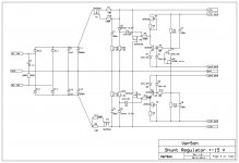
As per Mark's suggestion here's a version which should work in practice, utilizing the D45H11 output transistor (fitted on a heatsink). I'll leave it up to the inquisitive reader to dot all the is and cross all the ts.
Attachments
Updated schematic and BOM are here. To get better and more linear output impedance CCS (J2 and J3) is increased to about 10 mA and nfet used here should be chosed with the Idss of 10 mA or more. R2 and R9 are simple jumpers if Idss is close to 10 mA if higher then chose appropriate value to get about 10 mA.
Damir
Damir
Attachments
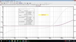
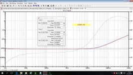
For those who like more choice here are more shunt mosfet combinations:
IRF510/IRF9510 or IRF530/IRF9530.
Bellow the output impedance plots for IRF510 and IRF530.
IRF510/IRF9510 or IRF530/IRF9530.
Bellow the output impedance plots for IRF510 and IRF530.
Attachments
Last edited:
Dadod
Sorry it is a little of your thread, but could you please send me ltspice library for IRF640 and IRF9640?
If possible also IRF530 and IRF9530.
TKS in advance.
Ronaldo
Here it is. IRF530 you can find in LTspice library.
Attachments
For those who like more choice here are more shunt mosfet combinations:
IRF510/IRF9510 or IRF530/IRF9530.
Bellow the output impedance plots for IRF510 and IRF530.
IRF510 looking really good impedance wise - great job. Now if only phase shift was say within 5 deg at 20khz I'd bite.
No doubt this is a really fine power source as described.
How much current can it deliver with IRF510?
//
Power supplies don't have Power Supply Rejection Ratio. Instead the term that is used is Line Rejection. It is defined as ||Vout|| / ||Vin|| at a certain frequency.... PSRR plot as a function of frequency with a broad band (1hz-1MHz) noise contaminated power source.
Sometimes Line Rejection is measured at many different frequencies, and the data is then presented as a scatter plot or a scatter plot with interpolating lines between discrete measurement points.
- Home
- Amplifiers
- Power Supplies
- Shunt regulator +-15V