I am not sure if both of those regulators are of the same type, could be that the difference is series verso shunt regulator?
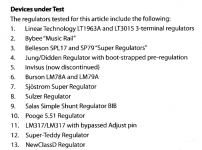
John Walton's article in Linear Audio carefully states exactly which regulators he is testing, see Figure 1 below. Pooge 5.51 was published in issue #1_1995 of The Audio Amateur magazine. (here is that article; the schematic you seek is Figure 3) Probably you are already very familiar with the Jung Super Regulator using AD797. If not there are several threads here on diyAudio which present its schematic.
The schematics will tell you, and I suspect you may find their answer surprising.could be that the difference is series verso shunt regulator?
_
Attachments
I'll second the requirement for having constant Zout and phase at least out to 50kHz or so
- If you really, really believe this, I have some good news for you: it is not very difficult to achieve. The POOGE 5.51 circuit was built back in 1995, without the use of any simulation whatsoever, and it meets your expectations. The circuit in post #49 with extremely flat Zout-versus-frequency, was slapped together in two hours using LTSPICE. If you invested a full week (40 hours) designing your own super-optimized circuit, I'm sure you could get dramatically better results.
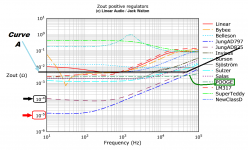
- I also have some better news for you: Walton's listening panel actually performed the experiment! They listened to a linestage powered by super-low-impedance regulators whose Zout begins to rise at very low frequency (Jung_AD797). AND they listened to the same linestage powered by medium-impedance regulators whose Zout remains flat and constant out to beyond 50 kHz (POOGE). The listeners reported huge differences in the audio quality. Have a look at the magazine or just the one article, and read what the listeners had to say. It's a darn good use of money IMHO.
Last edited:
I remember Jack Walton stating that "good" sounding regulators could not be correlated to low noise, low impedance, or high PSRR.
The burson for instance sounded good but performed poorly on the bench. Linear LDO lt1963 doesn't have stellar output Z performance, but sounded very good. Inversely the Salas sounded bad while having good performance.
Jack investigated further and found that distortion performance could be a clue.
The burson for instance sounded good but performed poorly on the bench. Linear LDO lt1963 doesn't have stellar output Z performance, but sounded very good. Inversely the Salas sounded bad while having good performance.
Jack investigated further and found that distortion performance could be a clue.
John Walton's article in Linear Audio carefully states exactly which regulators he is testing, see Figure 1 below. Pooge 5.51 was published in issue #1_1995 of The Audio Amateur magazine. (here is that article; the schematic you seek is Figure 3) Probably you are already very familiar with the Jung Super Regulator using AD797. If not there are several threads here on diyAudio which present its schematic.
The schematics will tell you, and I suspect you may find their answer surprising.
_
So, neither of those is shunt type. Borbely wrote that even simple shunt regulator sounds better then series one.
His article presents the actual correlation coefficients themselves. The measurement variable which gave the largest correlation between listener preference and measured result, was line rejection. As shown in Tables 8a and 8b (p.189), the Rsquared values ranged from 0.3 to 0.7. That's not perfect correlation. Nor is it chopped liver. Over the set of 13 regulators tested, the ones with good line rejection tended to sound good, and the ones with poor line rejection tended to sound poor. The correlation was not 0.99999 ("perfect"), nor was it 0.00000 ("completely unrelated").I remember Jack Walton stating that "good" sounding regulators could not be correlated to low noise, low impedance, or high PSRR.
The measurement variable which gave the smallest correlation between listener preference and measured result, was noise. Rsquared values ranged from 0.000 to 0.018. A damn fine example of "no correlation whatsoever". Over the set of 13 regulators tested, the ones with highest noise tended to be judged to sound just as good as the ones with lowest noise. Kind of surprising, no?
I'll let you look up the correlation coefficients between listener preference, and measured output impedance.
Borbely wrote that even simple shunt regulator sounds better then series one.
Do you believe him? He's allowed to be half-wrong occasionally, since he is human.
Here is a simple shunt regulator: resistor, zener diode, capacitor. Does it sound better than the series regulator that finished #1, best sounding, among the 13 series regulators that Walton tested?
I remember Jack Walton stating that "good" sounding regulators could not be correlated to low noise, low impedance, or high PSRR.
The burson for instance sounded good but performed poorly on the bench. Linear LDO lt1963 doesn't have stellar output Z performance, but sounded very good. Inversely the Salas sounded bad while having good performance.
Jack investigated further and found that distortion performance could be a clue.
Sounding bad is something we would have known by popular discontent after so many builds. Weird thing is that too many people use it for sounding good. Measuring good on top of that it should have rung a bell.
Jack may have had this (only one?) Kelvin output regulator when used for music under interference or oscillation on that preamp due to not knowing the recommendations and settings of its use. Not sure about that. Sure thing is it was hitting the current limit hard with the CCS setting he had and the load that he used in his THD later experiments.
@TNT and the rest of you that don't think this regulator is good enough, publish your own design and I'll buy a couple of PCB's so I can try'em out myself.

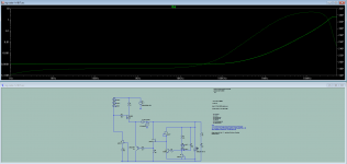
I spent a couple hours this morning, fiddling with modifications to dadod's positive shunt voltage regulator in post #1. I changed to a PNP emitter follower instead of a Pchannel MOSFET source follower, and fiddled with the error amp to get a different point on the gain - bandwidth tradeoff. The result is below. It shows that constant output impedance (both magnitude and phase) over a very wide range, is possible Whether this kind of extreme flatness is desirable, is perhaps another question.
_
The regulator in this thread is basically the SSLV topology and you don't have to go in much modification length to hit that 50kHz goal. Just use a BJT on output driven by a JFET source follower. It will go flat to 100kHz even. There is the BJT sans follower option in SSLV1.1 used for the BIB in its guide for years now. When using a buffer these regulators are getting more reactive about load and compensation so its not that practical to recommend them as general regulators if the user can't manage them per application. I know that by the V1.2R version practice and other experiments.
Attachments
The regulator in this thread is basically the SSLV topology and you don't have to go in much modification length to hit that 50kHz goal. Just use a BJT on output driven by a JFET source follower. It will go flat to 100kHz even. There is the BJT sans follower option in SSLV1.1 used for the BIB in its guide for years now. When using a buffer these regulators are getting more reactive about load and compensation so its not that practical to recommend them as general regulators if the user can't manage them per application. I know that by the V1.2R version practice and other experiments.
I did not want to complicate to much, in my opinion this is more then good enough, look post: http://www.diyaudio.com/forums/power-supplies/286425-shunt-regulator-15v-6.html#post4621345
By the way I think that Vbe is not enough voltage for a jfet work as good CCS, at least add one diode in bjt emitter.
I did take inspiration from yours shunt regulators and I wanted a bit simpler, improved and one adjustment for both polarity.
Yours shunt regulators are very good and very popular.
Its just better enough than a resistor to nest a low Vgs (off) Jfet in Vbe but its not exploiting it to its full. On the other hand lifting with a diode is not optimal either because it puts there its delta R. Best is to cross couple the Vrefs between polarities so to give the Jfets as much VDS you like. That thing works in double polarity symmetrical arrangements but when to also can have independent single polarity reg a Jfet is bit better than a resistor.
P.S. In Paradise Phono where the parallel part is SSLV again they used just resistor under Vbe. When not having low Vgs (off) low noise Jfets to spare its not a big loss to substitute a resistor. Vbe/R will determine the Ref mA.
P.S. In Paradise Phono where the parallel part is SSLV again they used just resistor under Vbe. When not having low Vgs (off) low noise Jfets to spare its not a big loss to substitute a resistor. Vbe/R will determine the Ref mA.
@TNT and the rest of you that don't think this regulator is good enough, publish your own design and I'll buy a couple of PCB's so I can try'em out myself.
I cant build a wristwatch - still, I have opinion on them and choose them carefully. I admire those who can. Sorry for derailing your thread dadod.
//
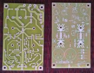
The boards are here. Please send me PM with PayPal email address and I can send PayPal Request a payment.
me 2 boards
brianco 2 single boards
jasse 4 single boards
Ryssen 2 single boards
arthur 2 boards
buzzforb 2 boards
androa76 1 board
tomekmad 4 boards
KVP 1 board
Damir
me 2 boards
brianco 2 single boards
jasse 4 single boards
Ryssen 2 single boards
arthur 2 boards
buzzforb 2 boards
androa76 1 board
tomekmad 4 boards
KVP 1 board
Damir
Attachments
Damir:
Please confirm the pre-shipping price.
Many thanks.
PCB price 7 EUR plus shipping (from 6 to 11 EUR depends of destination county and package weight.
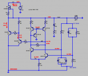
I spent a couple hours this morning, fiddling with modifications to dadod's positive shunt voltage regulator in post #1. I changed to a PNP emitter follower instead of a Pchannel MOSFET source follower, and fiddled with the error amp to get a different point on the gain - bandwidth tradeoff. The result is below. It shows that constant output impedance (both magnitude and phase) over a very wide range, is possible Whether this kind of extreme flatness is desirable, is perhaps another question.
_
@Mark,
I plugged your schematic into LTspice, but all I get is fW dissipation and pA currents all around, something must be missing from the schematic you posted? If you could fill in the blanks, or send me a PM with a few pointers, I'd appreciate it.
The diyAudio member who gives LTSPICE tutorials is "Mooly", check his posting history to find the appropriate threads. (this one might be a possibility)
I bet he recommends that the first thing you do is VIEW -> SPICE_ERROR_LOG . This is how you find out that your simulation calls for a "DN2540" MOSFET but your model library doesn't have any simulation parameters for DN2540.
Next I think you may want to check whether you've installed M1 backwards.
Next I imagine you'll want to run a .DC analysis or a .OP analysis and compare your voltages and currents against the right answers shown below.
_
Attachments
- Home
- Amplifiers
- Power Supplies
- Shunt regulator +-15V