Howdy
I want to build a 3 rail (+12V, +5V, +3.3V) quasi ATX power supply (circa 5A per rail capability). (I say "quasi" as I doubt it will meet the full spec even ignoring the lack of -12V.) I will be using a TPS3510 to manage the voltage monitoring and power good signalling.
The +12V/+5V/+3V3 lines should deliver no current to the motherboard until the power on (PSON) is asserted low by the motherboard. The TPS3510 monitors the voltages on the rails and sends a power good signal (PGO) when no under/over voltage condition exists.
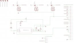
My power rails will be on all the time and so I need three switches to prevent power to the motherboard until PSON. The idea is that the rails pre the switch are always true to their required voltages and so upon PSON the TPS3510 sees good voltages and so sends PGO after the requisite delay. I was thinking this PGO signal could, in turn, be used to "turn on" this switch and I'm wondering whether their will be enough current in the circuit below to turn on the power mosfets via the VOM1271 photovoltaic mosfet drivers. See the circuit below. (As I write I am beginning to have a little doubt regarding the sequencing / structure but let's persevere for a moment.)
The recommended operating condition for the TPS3510 says maximum output sink current for PGO of 10mA. I understand this to mean that because PGO is held low if ever the voltages on the rails are not within range the maximum current at PGO can be 10mA and so the minimum value R14 can be is 500R. So when PGO is held high I've got 10mA to play with, so-to-speak. Pg 26 of the ATX power supply design guide describes the signal characteristics of this signal (the guide uses the notation PWR_OK) as:
So I believe I have 9.8mA of current I can direct to the three VOM1271 in series. If I read Fig 2 of the VOM1271 data sheet correctly, such a current should generate a voltage across the gate of the mosfet of around 7-8V. Am I right to look at Fig 1 of the data sheet for the IRF540 and see that this Vgs should be enough to provide for at least 5A of Ids for each of the 12V and 5V rails? Vgs of 3V3 is not depicted, however? Perhaps there are mosfets more applicable to this application?
Alternatively I could add a current source that's triggered by PGO to get more current across the VOM1271 and hence more Vgs on the mosfets. I've been reading up on current sources but obviously if I can avoid the complication it would be great.
Does the above make sense?
Now for the "structural" hesitation I mentioned above. Obviously the power rails are "on" all the time (and so I do not have a separate 5V standby) and PSON from the motherboard isn't 'igniting' the PSU but rather PGO is turning on the availability of current to the motherboard. Technically what should happen is that the voltage rails power up and have available current for the motherboard just prior to PGO and not just after. It seems many (most?) motherboards are somewhat insensitive to timing except to ensure the main power rails aren't delivering power until after PSON and so maybe this structure will be ok. If anyone has thoughts on this I'd appreciate it.
Regards
Steve
I want to build a 3 rail (+12V, +5V, +3.3V) quasi ATX power supply (circa 5A per rail capability). (I say "quasi" as I doubt it will meet the full spec even ignoring the lack of -12V.) I will be using a TPS3510 to manage the voltage monitoring and power good signalling.
The +12V/+5V/+3V3 lines should deliver no current to the motherboard until the power on (PSON) is asserted low by the motherboard. The TPS3510 monitors the voltages on the rails and sends a power good signal (PGO) when no under/over voltage condition exists.
My power rails will be on all the time and so I need three switches to prevent power to the motherboard until PSON. The idea is that the rails pre the switch are always true to their required voltages and so upon PSON the TPS3510 sees good voltages and so sends PGO after the requisite delay. I was thinking this PGO signal could, in turn, be used to "turn on" this switch and I'm wondering whether their will be enough current in the circuit below to turn on the power mosfets via the VOM1271 photovoltaic mosfet drivers. See the circuit below. (As I write I am beginning to have a little doubt regarding the sequencing / structure but let's persevere for a moment.)
The recommended operating condition for the TPS3510 says maximum output sink current for PGO of 10mA. I understand this to mean that because PGO is held low if ever the voltages on the rails are not within range the maximum current at PGO can be 10mA and so the minimum value R14 can be is 500R. So when PGO is held high I've got 10mA to play with, so-to-speak. Pg 26 of the ATX power supply design guide describes the signal characteristics of this signal (the guide uses the notation PWR_OK) as:
Logic level high: Between 2.4V and 5V output while sourcing 200uA
So I believe I have 9.8mA of current I can direct to the three VOM1271 in series. If I read Fig 2 of the VOM1271 data sheet correctly, such a current should generate a voltage across the gate of the mosfet of around 7-8V. Am I right to look at Fig 1 of the data sheet for the IRF540 and see that this Vgs should be enough to provide for at least 5A of Ids for each of the 12V and 5V rails? Vgs of 3V3 is not depicted, however? Perhaps there are mosfets more applicable to this application?
Alternatively I could add a current source that's triggered by PGO to get more current across the VOM1271 and hence more Vgs on the mosfets. I've been reading up on current sources but obviously if I can avoid the complication it would be great.
Does the above make sense?
Now for the "structural" hesitation I mentioned above. Obviously the power rails are "on" all the time (and so I do not have a separate 5V standby) and PSON from the motherboard isn't 'igniting' the PSU but rather PGO is turning on the availability of current to the motherboard. Technically what should happen is that the voltage rails power up and have available current for the motherboard just prior to PGO and not just after. It seems many (most?) motherboards are somewhat insensitive to timing except to ensure the main power rails aren't delivering power until after PSON and so maybe this structure will be ok. If anyone has thoughts on this I'd appreciate it.
Regards
Steve
Attachments
Last edited:
VOLTAGE turns on a mosFET.
The capacitance on the gate requires some current to charge up to the turn on voltage.
If you charge up the gate very slowly the gate draws virtually no current.
If you charge up the gate very fast, the gate draws lots of current.
It's the SPEED that you "turn on" that determines whether any current enters the gate.
I suppose you could use circuit simulation to measure the deltaQ needed to turn on each of the IRF540 MOSFETs "adequately" (giving whatever small Vin_to_Vout voltage drop you deem acceptable), at the max output current on each rail. One of the deltaQ values will be the largest of the three, and my money is on the +12V switch's deltaQ.
Now you can use your required switching delay (deltaT) to calculate the required output current of the photovoltaic driver:
I = deltaQ / deltaT
You probably want some safety-margin amount of excess current (33%??) to account for the facts that the IRF540 SPICE model is probably wrong (Murphy's Law), and that the photovoltaic current I is not independent of voltage, and so forth.
Simulation will also tell you how much VGS the MOSFET needs, to give you the Vin_to_Vout drop that you require. Add a volt, because Murphy's Law says that your MOSFET will be at the high end of the gate threshold voltage population distribution. Is the required VGS, more voltage than the worst case, puniest weakling photovoltaic driver can provide?
Logic level Mosfet
Hi Steve ,
A few concerns here .
Check the polarity of the VOM see my post http://www.diyaudio.com/forums/clas...ar-psu-dc-error-protection-4.html#post3943793
I would use a Logic level Mosfet like the IRFB3077 since your voltages are so low . They switch very good and fast with my "old Fashioned" PVI5010 couplers , which are far inferior to the VOM 1271
3 VOM's in series could be tricky on logic high if you have a max forward voltage on each LED in the VOM's , in the other extreme of low Vf's you'll need a series resistor or the max source current limit of your PGO chip is exceeded .
Would be wise to measure each couplers Forward voltage at 10 mA's and calculate a series resistor in any case to keep it below the chip max specs ..
Cheers ,
Rens
Read PVI1050 in stead of PVI5010
Edit time elapsed
Cheers ,
Rens
Hi guys
Thanks for the input. Re the VOM1271 pins, yep I picked this issue up from the other thread. I had simply grabbed the same device Piisami had done and so imported his error. Lesson to self: check the work for oneself. I will make the correction.
Re Mosfets, I had suspected there would be a better choice (as noted above). I'm still getting used to these things. I guess I could have searched for lower Gate Threshold Voltage?
Rens, let me see if I follow your argument:
- logic high -> current flows to VOM1271
- max LED forward voltage = 1.6V
- 3x1.6V > 5V input to first VOM1271 = problem
- logic level low -> TPS3510 needs to be able to handle the current being sunk to ground
- here my pull resistor R14 limits the circuit current to 10mA which is the maximum recommended operating condition for the TPS3510
- am I missing something else here?
Regarding the first issue, I find diode specs a bit confusing when thinking about their maximum voltage rating. Is this the "LED Input Ratings Reverse Voltage"? (If so it's the 'reverse' that I find confusing.) The VOM1271 has rated Vr of 5V. So it would seem a series configuration is doomed. (I can't supply 12V - the TPS3510 can handle the higher Vdd.)
On the other hand, with a parallel configuration I probably don't have enough current. So am I right to conclude I am probably forced to drop in a current source to 'grab' current from the 5V rail, such source turned on by the 5V PGO going high and supplying current to the 3 VOM1271 in parallel?
I appreciate the help
Steve
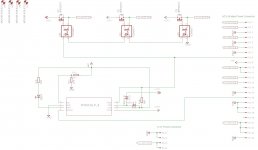
Going back to posts 6 and 8, does this work?
PGO goes high showing 5V on gate of Q4 which allows current to flow to the three VOM1271 which in turn activate the main switches Q1-3. Probably short a resistor or three...
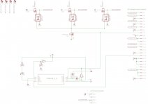
The first circuit can work ,but you'll need a limiting resistor in series with led's.
If the total forward voltage of the leds is 3*1.4V=4.2V this resistor should be (5-4.2)/0.01=80 ohm or higher
I doubt if Q4 will open in the second schematic as the gate source voltage is very low .
Cheers ,
Rens
...and see that this Vgs should be enough to provide for at least 5A of Ids for each of the 12V and 5V rails? Vgs of 3V3 is not depicted, however? Perhaps there are mosfets more applicable to this application?
Hi Steve
There seems to be a misconception here that no one has picked up on.
You don't need to worry about a Vgs of 3.3 V
The photovoltaic coupler "floats: the Vgs.
So the 3.3 V rail will still have the full 7 or so volts of drive.
So you should be fine on that issue.
Unless it's me that needs another coffee.
As pointed out, the IRF540 with 77 milliohm Rds is not ideal.
The latest from TI has a sub 1 milliohm Rds, seems remarkable to me.
Best wishes
David
Last edited:
Hi David, yes my original concern re the 3V3 rail was misguided as I was confusing Vds and Vgs. Learning here but making some sloppy mistakes in thinking while I am at it (as particularly evidenced by my inability last night to multiply 1.6 by 3!). However, I think the recommendation regarding the IRFB3077 is still appropriate. (Less Vgs to get them kicking.) Am I right to think of Rds as like inertia: the lower the Rds the more responsive the switch? The IRFB3077 has typical Rds of 2.8 milliohm.
... the IRFB3077 is still appropriate. (Less Vgs to get them kicking.) Am I right to think of Rds as like inertia: the lower the Rds the more responsive the switch? The IRFB3077 has typical Rds of 2.8 milliohm.
We all make mistakes, no problem, I was just concerned that no one had pointed it out.
Rds is more like friction than inertia, it's close to a simple ohmic resistance so the usual Ohms law calculation applies.
A couple of amps across 2.8 milliohm is only about 5 mV so the IRFB3077 or similar will be fine.
1 milliohm is probably lower than many ordinary switch contacts, which I find remarkable.
Best wishes
David
The first circuit can work ,but you'll need a limiting resistor in series with led's.
If the total forward voltage of the leds is 3*1.4V=4.2V this resistor should be (5-4.2)/0.01=80 ohm or higher
I doubt if Q4 will open in the second schematic as the gate source voltage is very low .
Cheers ,
Rens
Hi Rens
Isn't the constraining factor the amount of current PGO can sink when held low? That's 10mA. As a result the series resistor R14 needs to be 500R (5/0.01). When PGO is held high then the current across the 3 VOMs is a mere circa (5-3x1.4)/500 = 0.16mA. (In fact it is lower to the tune of the current drawn by the mobo through PGO i.e.120uA to 200uA.)
Hence I think I'm still lacking a good deal of current. Or am I missing something obvious again?
Regards
Steve
the mosfet does not need current to pass.
It only needs current to charge up the gate capacitance as it turns on.
Once turned on no current passes into the gate.
The SPEED of turn on is limited by how fast you can charge up the gate. That fast charging needs more current. But then the current stops.
It only needs current to charge up the gate capacitance as it turns on.
Once turned on no current passes into the gate.
The SPEED of turn on is limited by how fast you can charge up the gate. That fast charging needs more current. But then the current stops.
When PGO is held high then the current across the 3 VOMs is a mere circa (5-3x1.4)/500 = 1.6mA. (In fact it is lower to the tune of the current drawn by the mobo through PGO i.e.120uA to 200uA.)
corrected
still not enough current through the VOM diode to its Voc > Vth of the IRFB3077.

Hmm…maybe if I cascade the rail turn-on. PGO turns on the 5V rail and the 5V rail turns on the other VOMs…something for tomorrow...
- Status
- This old topic is closed. If you want to reopen this topic, contact a moderator using the "Report Post" button.
- Home
- Amplifiers
- Power Supplies
- Enough current to turn on 3 mosfets?