Mark mentioned an Excel table with snubber data for a number of transformers; the last version posted is here:
http://www.diyaudio.com/forums/powe...-using-quasimodo-test-jig-76.html#post4574586
My current table contains the snubber data for 16 transformers.
I started gathering these data hoping to arrive at a correlation between the transformer specs and the Rs value, helping thus people who do not have a scope to calculate the above value without performing the measurement. I must admit that I haven't arrived at a useful correlation, but it may be that I haven't tried hard enough.
However, the table shows a very good agreement between the theoretical model as formulated by Jim Hagerman and Mark, and the measurements performed by means of Quasimodo. So instead of dialing the trimmer I now measure the parasitic inductance (still need the jig for that) and the secondary resistance, and then obtain the snubber value from the last row in Excel sheet, where the theoretical formula is implemented.
I've built more than a half of the transformers listed in the table into different projects, and checked the secondary waveforms with a scope in each of them. I observed that the Rs value that gives the same damping in a loaded transformer, i.e. within a working PSU, is almost always higher by 20 to 50% than the one determined by the jig and/or the theory.
Regards,
Braca
Hi Braca,
Thanks for posting about that. This is the type of thing that I would like to try as well. Since it can be expected that there will be quite a bit of variety between transformers of different design and very low and very high power designs, I would investigate only toroidal power transformers with a VA rating of more than 100W and secondary voltage of at least 25V. I could try to use examples from the Antek product line (US manufacturer of toroidal transformers like Avel-Lindburg). Your table only includes one transformer in this VA range.
Thanks for posting about that. This is the type of thing that I would like to try as well. Since it can be expected that there will be quite a bit of variety between transformers of different design and very low and very high power designs, I would investigate only toroidal power transformers with a VA rating of more than 100W and secondary voltage of at least 25V. I could try to use examples from the Antek product line (US manufacturer of toroidal transformers like Avel-Lindburg). Your table only includes one transformer in this VA range.
Charlie -- I have a spare V4 Quasimodo board from the group buy I'll sell you at my cost. If you can wait a couple more days I might even have the parts to populate it - I don't know the cost of parts but the labor would be free. Looks like a good cause. PM if you're interested.
Phil
Phil
Gents, when Rs is too large the resonant circuit will be underdamped. This is a problem because the resonant oscillation still exists and will radiate into your circuitry. When Rs is smaller than the critically damped value, that is over-damped, it will likely have more current through it and therefore need to be a higher wattage. When over damped there is no risk of resonant oscillation and therefore no radiated noise. This is good.
Cs is chosen to be effectively a short circuit at the resonant frequency and have enough impedance at your mains frequency to limit the current in Rs to a reasonable level.
Cx is chosen to far exceed the transformer and diode parasitic capacitance and thus decrease frequency and increase the wavelength of the resonant current so that wiring length between transformer and rectifier is a less effective radiator.
With this in mind I simply use 100n and 100ohm without Cx. For all the transformers I have used this is grossly over damped and my power supplies are silent. Hope this helps....
Yep, Morgan Jones tried to find a "Universal Snubber" in his Linear Audio article (link) and concluded, there's no such thing. But remember he's the author of Valve Amplifiers, Fourth Edition, perhaps he works with different kinds of transformers.
... I simply use 100n and 100ohm without Cx. For all the transformers I have used this is grossly over damped ...
Hi Johno,
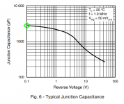
In addition to the VF30100S diode in post #1175 whose zero bias capacitance is 2.7 nF, the Linear Audio test also included the VSB1545 (see Figure 1 below) with 2.8 nF of zero bias capacitance.
The closest value I could scrounge in my lab this morning was 2.3 nF; I put that capacitor into my Quasimodo PCB in the Diode Capacitance position. Then I installed Cs=100nF and Rs=100 ohms per your suggestion.
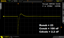
The transformer was a toroid from Triad Magnetics: (link to .pdf datasheet). It was medium sized (160 VA) and medium voltage (two 15VAC secondaries). {Morgan Jones might call this "ridiculously low voltage" but I bet his heaters run on 6.3VAC which is lower still}
Results below.
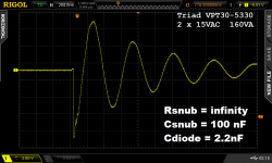
With the 100 ohm Rs removed from its socket, there is no snubber at all, and I got the waveform in Figure 2. Plenty of ringing.
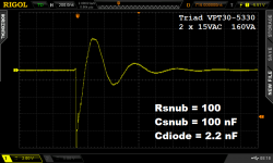
With 100 ohms installed in its socket, your snubber is in place, and I got the waveform in Figure 3. Less ringing but not zero, and certainly not "grossly over damped".
I removed the 100 ohm resistor and replaced it by a 25 turn trimmer pot. I dialled this pot to give approximately critical damping (zeta ~ 1.0), and got the waveform in Figure 4. Then I measured the pot to see what resistance gave zeta = 1.0 damping; the answer was: 23 ohms.
Best regards,
Mark Johnson
edit: yikes! I wrote "Cdiode = 2.2nF" on the scope photos but that's incorrect; it was actually 2.3nF.
_
Attachments
Last edited:
There is a Group Buy that intentionally purchased lots of extra v.3 (SMD) and v.4 (thru hole) Quasimodo blank PCBs. Head on over to the Group Buy area of the forum and see whether they still have inventory. It's a benefit for member Planet10 who was in the hospital several months; any revenue that exceeds costs, goes to a fund to defray their expenses.
.....Anyone else here in the USA have an extra board?
Support to Planet10 via the group buy think is great but funding can also be done here should some deside (link Fundraiser for Ruth de Fehr by Bonnie Scott : For Ruth & Dave), else can say got me a v4 from USA via member dsolodov (see post 468) all components is included and packed into practical numbered small bags.
Last edited:
It is a lot of money. It is a LOT of money. Don't even think of buying, without consulting your shaman, your life coach, your horoscope, your crystalline aura, and your personalized Google Fraud Detection Algorithm. Don't let anybody pressure you into paying a huge amount, until you have done your own research (your own self) and achieve your own peace of mind. YOU control the money and YOU control the timeline. The "worst" that can happen is, that someone else buys what you leisurely decided to bid for. But how is this "bad"? What injury has been done to you? You still have your skull, you still have your pride, you still have your money; who cares what somebody else has (or has not) purchased?
Last edited:
What differences are there between the Quasimodo and the CheapoModo boards?
Post the two* schematics side by side and I will help you circle the differences in red. Post #1 of each thread tells you where to find the schematics.
Or *three schematics if you are interested in QMv.3 versus QMV.4 versus CM
You did exactly the right thing and exactly what I hoped DIYA members would do after reading the Quasimodo design note. However, some people are anxious and nervous, lacking the confidence to build a board themselves starting from nothing but a known-good schematic diagram. These folks strongly prefer to buy a PCB (or a PCB + kit), because it isn't nearly as frightening as designing & debugging their own board. Even a small board like Quasimodo / Cheapomodo.I am confused. I built a cheap version alternative snubber testing jig in dead bug style and measured and found exact snubber component value. Why should I build Quasimodo if simpler version is adequate? Is it really more accurate?
Dead bug style construction might even be preferable in this case, because it gives a very low impedance groundplane. Congratulations!
- Home
- Amplifiers
- Power Supplies
- Simple, no-math transformer snubber using Quasimodo test-jig