Nine thousand pieces in stock: (link)
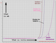
Or you could commence a hunt, using parametric search on distributors' websites. Buy five pieces each of the most promising three or four candidates, then measure the Vfwds using a temperature-stable 10mA current source (curve tracer not necessary). See whether any of them beats the 1N5819. I'm sure at least one of them will.
Or you could commence a hunt, using parametric search on distributors' websites. Buy five pieces each of the most promising three or four candidates, then measure the Vfwds using a temperature-stable 10mA current source (curve tracer not necessary). See whether any of them beats the 1N5819. I'm sure at least one of them will.
@MJ,
thans for link, my quick search was only for europe because I had in the last time some trouble with our customs. I also tried a search at digikey.de but i didn't found this I don't know why.
Thanks again I will order another v4 board.")
Octopart, wow that was new for me, cool search engine!
thans for link, my quick search was only for europe because I had in the last time some trouble with our customs. I also tried a search at digikey.de but i didn't found this I don't know why.
Thanks again I will order another v4 board.
Octopart, wow that was new for me, cool search engine!
Thank you Mark Johnson for a genious circuit and a beautifully documented description of the function.
I have one question which might be stupid/obvious, but which I couldn't find an explanation for, so if you or anyone could clarify it, I would be happy:
Why are we reaching for a dampened response at 120/100 Hz and not 60/50 Hz ?
I mean: we haven't rectified the signal yet, and we would probably want the dampening to happen at 60/50 Hz, right?
Is it because we want to see one cycle /zeta=1 at double the frequency so that we know the response will be overdamped at the actual frequency?
Change the DIPswitch setting on V4; this changes Quasimodo's square wave oscillator frequency. You can measure the oscillator's new frequency by counting grids on your oscilloscope face (some scopes have frequency measurement already built-in). Find out whether changing the square wave oscillator frequency, changes the optimum value of snubbing resistance. Maybe the optimum snubber remains optimum and unchanged, no matter what oscillator frequency is used. (as long as it stays well below omega_n in equation A.10 of the Quasimodo design note).
To perform this experiment on V3, temporarily tack-solder a 20K resistor in parallel with R2=39K to change the square wave oscillator frequency.
To perform this experiment on Cheapomodo, temporarily tack-solder a 20K resistor in parallel with the 47K resistor which connects to the 555 chip's pins 6 and 7. This will change the square wave oscillator frequency.
I am happy to help you understand your experimental results.
Please post oscilloscope photos of your Quasimodo driving a transformer in two configurations: (A) with the square wave oscillator set to 120 Hz {all four DIP switches open-circuit}; (B) with the square wave oscillator set to 600 Hz {DIP switch 1_to_8 short-circuit; other three DIP switches open-circuit}.
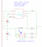
I have highlighted DIP switch 1_to_8 in the schematic fragment below.
The LMC-555's oscillation frequency in this circuit is: fosc = 1/(1.4*R*C) , where "C" is capacitor C4 and "R" is the resistance that charges and discharges C4. If we arrange the switches such that R=7.96Kohms and C=0.15uF, then fosc = 598 Hz.
_
Please post oscilloscope photos of your Quasimodo driving a transformer in two configurations: (A) with the square wave oscillator set to 120 Hz {all four DIP switches open-circuit}; (B) with the square wave oscillator set to 600 Hz {DIP switch 1_to_8 short-circuit; other three DIP switches open-circuit}.
I have highlighted DIP switch 1_to_8 in the schematic fragment below.
The LMC-555's oscillation frequency in this circuit is: fosc = 1/(1.4*R*C) , where "C" is capacitor C4 and "R" is the resistance that charges and discharges C4. If we arrange the switches such that R=7.96Kohms and C=0.15uF, then fosc = 598 Hz.
_
Attachments
Last edited:
Thank you Mark Johnson for a genious circuit and a beautifully documented description of the function.
I have one question which might be stupid/obvious, but which I couldn't find an explanation for, so if you or anyone could clarify it, I would be happy:
Why are we reaching for a dampened response at 120/100 Hz and not 60/50 Hz ?
I mean: we haven't rectified the signal yet, and we would probably want the dampening to happen at 60/50 Hz, right?
Is it because we want to see one cycle /zeta=1 at double the frequency so that we know the response will be overdamped at the actual frequency?
Although the snubber is before the rectifiers it is the rectifier switching action at 120hz that is causing the transformer to ring.
Although the snubber is before the rectifiers it is the rectifier switching action at 120hz that is causing the transformer to ring.
....now the penny dropped! Thank you

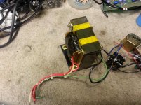
I found an interesting thing when using Quasimodo on this center-tapped PS Audio power transformer. The correct resistance value for one of the windings turned out to be 30 ohms, while the other winding required 68 ohms. Ignoring the center tap wire and checking the entire secondary at once yielded a value of 92 ohms.
So it looks like the two secondary windings on a centre-tapped transformer can have different optimum snubber values. I suppose that this makes sense, since one secondary would be wound over top of the first, resulting in a different coil diameter and therefore a different inductance value. So I will be checking *both* secondaries individually on the center-tapped transformers that I test with Quasimodo from now on.
Take care,
Doug
Attachments
Has anybody used Quasimodo on high voltage power supplies on electrostatic speakers? I am thinking of trying to snubberise my Acoustat interfaces.
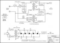
Other than compensating for the very high voltage rating needed for the capacitors, it seems like it should be straightforward. But I am wondering if the capacitors in the voltage multiplier would effect things at all. They are connected directly to the transformer on one side of each capacitor as shown in the below schematic.
Any thoughts?
Take care,
Doug
Attachments
I imagine that running a simulation can tell you whether the voltage multiplication capacitors do, or do not, influence the secondary's oscillatory ringing. Run it once with C=3300pF and again with ten times larger C. If the ringing frequency changes by sqrt(10) = 3.1X, you know the V.M. capacitors have an influence. If the ringing frequency doesn't change, the V.M. capacitors have no influence.
I've never attempted to snub a 750VAC transformer myself so I have no specific advice to give, except perhaps: be sure to calculate the power dissipation in the snubber resistor! It might be surprisingly large.
I've never attempted to snub a 750VAC transformer myself so I have no specific advice to give, except perhaps: be sure to calculate the power dissipation in the snubber resistor! It might be surprisingly large.
Design note p.12:
... center tapped transformer ... A skeptic would assume the two windings are not identical, and so a skeptic would optimize the top snubber, then separately optimize the bottom snubber. ...
I did read in the design note that you are not a skeptic. I, however, am very much one, especially after finding such a big difference between the windings on this transformer!
I imagine that running a simulation can tell you whether the voltage multiplication capacitors do, or do not, influence the secondary's oscillatory ringing. Run it once with C=3300pF and again with ten times larger C. If the ringing frequency changes by sqrt(10) = 3.1X, you know the V.M. capacitors have an influence. If the ringing frequency doesn't change, the V.M. capacitors have no influence.
I've never attempted to snub a 750VAC transformer myself so I have no specific advice to give, except perhaps: be sure to calculate the power dissipation in the snubber resistor! It might be surprisingly large.
OK, I've never actually used a circuit simulation program before, maybe I should get with the 21st century and download something.
Take care,
Doug
Hi All,
I’ve recently built a Quasimodo v4 through hole board and been learning to use it (and an old analogue oscilloscope) – I am new to electronics. I have some questions that hopefully someone can help me out with. I’ve waded my way through 40 odd pages of the thread on this topic which has helped me out somewhat; if the answers to my questions are on the pages I’m yet to read, perhaps someone could point me in the right direction.
Mark posed the question early on asking about what the dip switches did (I’m sure this has been answered in the pages I’m yet to read), but what I’ve found so far is that they make a dim o’scope trace less dim. Whether this is the designed intent or not I have no idea, but I’m guessing that this is the special thing built in to help those of us with analogue scopes who get dim traces.
The questions:
1) The design note (p12) mentions that using two channels on the o’scope is the best way of using Quasimodo — connect ch1 to the MOSFET drain pin and ch2 to transformer secondary. It also mentions that a single channel can be used by connecting the probe to the transformer node. However the v4 board has a pinout labelled as ‘scope’ and I’ve noted in photos of other users that they appear to be connecting the scope to that pin and only on one channel. This has confused me as to how I should be measuring — should I use 2 channels, 1 channel connected to the transformer node, or 1 channel connected to the scope pin?
2) Despite not being sure if I’m measuring correctly, I have taken some measurements of various transformers by connecting to the ‘scope’ pin and a ground pin (I only have 1 probe) and get the horizontal Christmas tree squiggly pattern as per the images in the design note which decrease to the optimum zeta = 1 line when I adjust Rs. I have measured 4 different transformers, 2 x E cores and 2 x toroids. All primaries and secondaries not being measured were shorted. Here are my results:
a. 100VA E core, Rs = 190ohms
b. 200VA E core, Rs = 90ohms
c. 600VA Toroid, Rs = 16 ohms
d. 2000VA Toroid, Rs = 13ohms
Both E Cores seem to fall in the range that others have reported as being values needed for Rs and also fall in the 50 – 500 ohm range that, I think, Mark points out somewhere. The toroids, however are very low. If I have used Quasimodo correctly, can someone help me understand what the low Rs values for the toroids mean? Are they reliable, should I adjust Cx and Cs for some reason?
Any help greatly appreciated.
There is certainly a tension between (A) lazy newcomers who prefer not to read 1100 prior postings, "I just want you to answer MY questions, right now!!"
and (B) weary oldtimers who have read and answered those same questions several dozen times.
What's the best way to resolve this tension? I doubt there's a single universal answer which makes everyone equally happy. Life is like that.
and (B) weary oldtimers who have read and answered those same questions several dozen times.
What's the best way to resolve this tension? I doubt there's a single universal answer which makes everyone equally happy. Life is like that.
My deepest thanks for your wise words Mark. And, please, let me take this opportunity to thank you most profusely for the effort and time you have obviously put into this device and making its design so freely available. Without persons such as yourself, forums such as these would be such poorer places.
Yes, I can certainly appreciate that tension you speak of and empathise with your feelings on such an issue; there’s nothing worse than idle laziness, especially in the new and coming. It’s much like the tension between (A) a not so lazy newcomer (who will eventually make their way through the 1100+ previous postings) eagerly wanting to make sure they are on the right path in their new hobby because, as for all of us, time is a diminishing and precious quantity and (B) having to negotiate the acerbic wit of long time forum members who automatically assume that posted questions are directed specifically at them rather than remain silent if the ebb and flow of forum life has worn them weary. Similarly to your own observations, I doubt a universally acceptable method of reconciling such tension exists.
Hopefully other, less weary, members might be inclined to provide a guiding hand to those of us just starting out. After all, everyone has to start somewhere.
Mark, I think the easiest way to mitigate the tension would be to add a frequently asked questions attachment to the application note.
We can make punishment: next person who ask a question that has been answer many times has to go through all the thread and compile the list
D.
We can make punishment: next person who ask a question that has been answer many times has to go through all the thread and compile the list
D.
- Home
- Amplifiers
- Power Supplies
- Simple, no-math transformer snubber using Quasimodo test-jig