Hi
I have just bought & received a V4 PCB from the group buy.
Looking through the app notes I notice that the normal test frequency is set at 120Hz.
As I live in the UK I was interested in setting the frequency to 100Hz to match the UK mains frequency of 50Hz.
Would I be correct to change the R3 39K resistor for a 47K and would this make any difference to the test results?
Regards Xoc1
LTSPICE includes a simulation model of a 555 in its "Misc" library. You can use that, and/or the equations in the LMC555 datasheet, to predict the oscillation frequency when the timing resistor is R ohms and the timing capacitor is C farads. Protip: doublecheck the Intersil ICL7555 datasheet (CMOS 555 equivalent) for another confirmation you've got the right equations.
Or you could try out your Quasimodo on a real transformer while fiddling around with the DIPswitch settings. Maybe you'll find that Quasimodo at 600 Hertz oscillation frequency, gives the same answer as Quasimodo at 120 Hertz oscillation frequency. {I know which way I'm betting}. If it does, then ask yourself why 100 Hertz will give a different answer than 120 Hz or 600 Hz.
Or you could try out your Quasimodo on a real transformer while fiddling around with the DIPswitch settings. Maybe you'll find that Quasimodo at 600 Hertz oscillation frequency, gives the same answer as Quasimodo at 120 Hertz oscillation frequency. {I know which way I'm betting}. If it does, then ask yourself why 100 Hertz will give a different answer than 120 Hz or 600 Hz.
I have yet to build my PCB. I just wondered if a little customisation of the frequency would be beneficial.
I am a mechanical design engineer. I did use the data sheet for the ICL7555 to calculate the frequency/resistance values. But have never used LTspice.
I understand your stance. It is D-I-Y audio after all.
A bit like members who ask me awkward questions abut my subwoofer designs without ploughing through the 2500 posts in my TH18 design thread!")
Regards Martin
I am a mechanical design engineer. I did use the data sheet for the ICL7555 to calculate the frequency/resistance values. But have never used LTspice.
I understand your stance. It is D-I-Y audio after all.
A bit like members who ask me awkward questions abut my subwoofer designs without ploughing through the 2500 posts in my TH18 design thread!
Regards Martin
I suggest you stuff and solder your board strictly following the B.O.M. and schematic attached to post #1 of this thread, with no parts value modifications. When your board is debugged and working, and when you have connected it to a transformer and oscilloscope, your own observations of its behavior on your own oscilloscope will tell you why it is, or why it is not, important to run the Quasimodo oscillator at a strict 2X multiple of your electric company's mains frequency.
I gently recommend you assume, temporarily, that Quasimodo was designed by someone who intended to use it with 50 Hz mains transformers, AND with 60 Hz mains transformers, AND with dual mode transformers rated both 50Hz/60Hz, AND with aviation 400 Hz mains transformers like this one. Temporarily assume the final result met these goals. As soon as you build your own Quasimodo you can do some experiments yourself, to verify or refute this assumption. You will not be the first person to do so! But it's oh so much work to go back and find their posts in this dauntingly long thread. Better to experiment yourself and get your own personal Eureka! moment.
I gently recommend you assume, temporarily, that Quasimodo was designed by someone who intended to use it with 50 Hz mains transformers, AND with 60 Hz mains transformers, AND with dual mode transformers rated both 50Hz/60Hz, AND with aviation 400 Hz mains transformers like this one. Temporarily assume the final result met these goals. As soon as you build your own Quasimodo you can do some experiments yourself, to verify or refute this assumption. You will not be the first person to do so! But it's oh so much work to go back and find their posts in this dauntingly long thread. Better to experiment yourself and get your own personal Eureka! moment.
Mark you are the epitome of understated, gentle criticism.
117 (and counting) pages is a lot to wade through, but it's not as bad as some. The take-away surely is this is a popular topic and you have done well to start it and continue participating, despite the repeated questions and repeated answers to some obvious questions.
I think another approach would be to suggest people start to learn how to master the DIYAudio Search function ... like so many things, it's quite powerful, but only if you take advantage of that power. Typing some common words into the simple search field is not "take[ing] advantage of that power".
Or, put another way ... "we get the search results we deserve".
Am eagerly awaiting a PCB v4, so who knows, maybe I will have to eat my words ;-)
Regards, in any case, and thank you.
Last edited:
There is certainly a tension between (A) lazy newcomers who prefer not to read 1100 prior postings, "I just want you to answer MY questions, right now!!"
and (B) weary oldtimers who have read and answered those same questions several dozen times.
What's the best way to resolve this tension? I doubt there's a single universal answer which makes everyone equally happy. Life is like that.
The first page can be used as a summary page.
OR
Someone can do as I did, first I created a wiki page that disappeared when
the power that be thought it would be better to organize the wiki.
So, I ended up putting it into my blog here at DIY. I think it is number three or
number four.
I had strange feelings when doing it and setting up the links etc. I mean
I had to wade through 1000's of pages and had to try and boil it down
then provide links to relevant posts of the discussion.
What feelings? Holy smokes I spent weeks reading, studying, etc.
and of all the good work some very fine folks did, all any one
else has to do is just burn through the blog and save weeks or months of time.
And then, well this is the DIYAudio site. The purpose is to share knowledge
and enthusiasm for it. Helping others by way of our efforts is a good thing.
It is what it is.
Cheers,
Sorry if this has been covered before, I have read many of pages, but it's been a while now.
I have successfully.... deringed.....several power transformers with my Quasimodo, and am most pleased with the results.
But now I have a problem with a supply choke that seems to be ringing. This is an great big choke made in 1948 for a PSE 6V6 amp. I haven't measured the Hy yet, but guess it is up in the 20Hy range, so far bigger than any supply secondary.
My question is, which capacitors do you sugest I start off with in the quasimodo, and do you think I need to change the sweep potentiometer value as well ? Would it help if I measured the Hy of the choke first ?
I'd be pleased to hear any thoughts on the subject, or references to posts that might cover the topic.
Thanks.
Quasimodo & Cheapomodo stimulate oscillatory ringing upstream of the rectifier(s). Although I cannot read the schematic you posted, I'm guessing it has a great big choke downstream of the rectifier(s). In that case you will need to invent a new measurement & tuning approach, which might or might not include your Quasimodo PCB.
Quasimodo & Cheapomodo stimulate oscillatory ringing upstream of the rectifier(s). Although I cannot read the schematic you posted, I'm guessing it has a great big choke downstream of the rectifier(s). In that case you will need to invent a new measurement & tuning approach, which might or might not include your Quasimodo PCB.
Okay, thanks for your answer Mark. I will just try some of the more traditional methods then. Morgen Jones's method perhaps.
I'll bet if you showed the full schematic of your power supply to your circuit design mentor, she could suggest to you: which 2 measurements to perform, in order to acquire all the information needed to make an acceptably accurate LTSPICE simulation.
Then once you've got it in simulation, you can watch it ring and ring and ring, and also watch it gradually stop ringing as you add or delete components, and change their values. Then you can find "the cliff of death" in simulation, where the PSU self destructs, and choose component values somewhere in the middle between "where it just barely stops ringing" and "the cliff of death".
Then once you've got it in simulation, you can watch it ring and ring and ring, and also watch it gradually stop ringing as you add or delete components, and change their values. Then you can find "the cliff of death" in simulation, where the PSU self destructs, and choose component values somewhere in the middle between "where it just barely stops ringing" and "the cliff of death".
Recently I started a thread to get some input on the pros and cons of monolithic bridge rectifiers. That led to a discussion about ringing (they are evidently pretty bad in this regard) and snubbing (to prevent the ringing), which led to Mark bringing up his QuasiModo jig. I have been learning about that, and Mark's "C+CR" network, and have a couple of questions.
I understand how the QuasiModo jig works, and seem to understand the purpose of the components in the "C+RC" snubbing network. But I am having a really hard time understanding WHY you really need to use the jig (except that it permits you to do the scope measurements). I will explain.
From what I understand the choice of component values in the C+RC network is as follows:
Cx: this is the capacitor (without series R) in parallel with the transformer secondary. The value of this capacitor can be chosen so that it is much larger than both the transformer leakage capacitance and the diode's capacitance. A typical value might be 10nF (or more, e.g. tens of nF).
Cs: this is the capacitor of the RC branch of the snubber network. According to Mark's heuristic, you choose this value to be much greater than Cx, he suggests at least 15 times greater.
Rs: this is the resistor of the RC branch of the snubber network. In Mark's jig, he uses a 1k trimpot to adjust this resistor to get an "optimum" time domain response that he calls "critically damped". I have seen reported values in the range of of 47R-470R.
Choose a value for Rs that is too high and there will not be enough damping; too low and there will not be enough damping either. You need to optimize! Or do you?
It seems to me that Rs is the ONLY really adjustable component in the network. It seems that the values for Cx and Cs can be chosen heuristically, as I explain above. If you choose Rs "wrong" then your snubber will be "suboptimal", however it seems that as long as you are not WAY OFF by an order of magnitude or more on this value, you will still get some snubbing action. If I want to use a monolithic bridge there will a lot of ringing to snub, so even a non-optimal snubber would be useful.
I started to consider how to guesstimate the value of Rs. I looked at various reports of the optimum value of Rs found using the QM jig. From other sources on RC snubbers I found that common values of R lie between 10R and 100R (within this decade at least). So the questions I am left with are:
- Just how bad will the performance of the C+RC snubbing be if R is not chosen to be optimum, but rather it is just chosen to be some value within the expected range?
- Would the difference between the optimized snubber and one that is close but not optimized be an extra one or two cycles of ringing?
- What is the relationship between the amount of damping and the error in choosing the value of Rs?
- If the sensitivity in the error of Rs is not high, could a heuristic for choosing Rs be developed?
It would be a reasonably straightforward exercise in computer programming with loops, to calculate an (estimated!) upper bound and lower bound for optimal {"optimal" defined by me to mean: damping = zeta = 1.0} snubber component values.
Merely iterate over all possible secondary leakage inductances, secondary self-capacitances, rectifier capacitances, and Cx values. In each case calculate the value of Rs which gives zeta=1.0, using the equations in Appendix A of the Quasimodo Design note. You can neglect the value of Cs in these calculations, since (a) it doesn't even appear in the equations; and (b) it doesn't chew up a Degree Of Freedom anyhow, because Cs=15Cx works adequately well in snubbers with zeta=1.0.
Somewhere in this thread is a half dozen posts from a DIYA member (forgot their handle, sorry!), who made spreadsheets tabulating the Quasimodo derived optimal snubbers for a couple dozen transformers. You could use those numbers to run the equations in reverse and extract secondary leakage inductances. Or you could post a message here asking DIYA members "What is the HIGHEST value of Quasimodo-optimized snubber resistance that you have ever seen?" Then also "What is the LOWEST value of snubber resistance that you have ever seen?" Add in a bit of safety guardband because an infinite set has more variation than a finite subset.
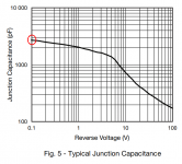
For diode capacitance, the lowest capacitance rectifier I've encountered is the lowly 1N4005, at 8 picofarads. The highest capacitance rectifier diode I've encountered, is the VF30100S, at 2700 picofarads (!!), pictured below. Remember that a bridge rectifier includes four diodes and remember that at the instant of ringing (when it matters), all four diodes operate at different bias conditions hence different capacitances. So you'll need to figure out the four bias points, grab the four capacitances from the curve, and add them up.
Use all of this information, to dream up your own "CharlieLaub No-Measurement Algorithm for Snubber Component Selection". It might be a single Universal Snubber, where the same component values are used for all power supplies. No matter what transformer the designer picks, no matter which rectifiers the designer picks, the recommended snubber components are always the same: Rs=VALUE1, Cs=VALUE2, Cx=VALUE3 (V3 might be zero! It was for Morgan Jones.). Then run that through the loopety loop calculation again, with all possible transformers and all possible rectifiers, and calculate what the damping factors turn out to be. Maybe they're great.
But perhaps this is too restrictive. Although you don't know the transformer inductance and capacitance, (and you can't know it without measurement), you DO know the rectifier capacitance. It's right there on the datasheet! So maybe your Algorithm for Snubber Component Selection gives different component values when rectifier capacitance changes. That would still be a No-Measurement procedure. Then run that through the loopety loop calculation again, with all possible transformers and all possible rectifiers, and calculate what the damping factors turn out to be. Maybe they're great.
_
Merely iterate over all possible secondary leakage inductances, secondary self-capacitances, rectifier capacitances, and Cx values. In each case calculate the value of Rs which gives zeta=1.0, using the equations in Appendix A of the Quasimodo Design note. You can neglect the value of Cs in these calculations, since (a) it doesn't even appear in the equations; and (b) it doesn't chew up a Degree Of Freedom anyhow, because Cs=15Cx works adequately well in snubbers with zeta=1.0.
Somewhere in this thread is a half dozen posts from a DIYA member (forgot their handle, sorry!), who made spreadsheets tabulating the Quasimodo derived optimal snubbers for a couple dozen transformers. You could use those numbers to run the equations in reverse and extract secondary leakage inductances. Or you could post a message here asking DIYA members "What is the HIGHEST value of Quasimodo-optimized snubber resistance that you have ever seen?" Then also "What is the LOWEST value of snubber resistance that you have ever seen?" Add in a bit of safety guardband because an infinite set has more variation than a finite subset.
For diode capacitance, the lowest capacitance rectifier I've encountered is the lowly 1N4005, at 8 picofarads. The highest capacitance rectifier diode I've encountered, is the VF30100S, at 2700 picofarads (!!), pictured below. Remember that a bridge rectifier includes four diodes and remember that at the instant of ringing (when it matters), all four diodes operate at different bias conditions hence different capacitances. So you'll need to figure out the four bias points, grab the four capacitances from the curve, and add them up.
Use all of this information, to dream up your own "CharlieLaub No-Measurement Algorithm for Snubber Component Selection". It might be a single Universal Snubber, where the same component values are used for all power supplies. No matter what transformer the designer picks, no matter which rectifiers the designer picks, the recommended snubber components are always the same: Rs=VALUE1, Cs=VALUE2, Cx=VALUE3 (V3 might be zero! It was for Morgan Jones.). Then run that through the loopety loop calculation again, with all possible transformers and all possible rectifiers, and calculate what the damping factors turn out to be. Maybe they're great.
But perhaps this is too restrictive. Although you don't know the transformer inductance and capacitance, (and you can't know it without measurement), you DO know the rectifier capacitance. It's right there on the datasheet! So maybe your Algorithm for Snubber Component Selection gives different component values when rectifier capacitance changes. That would still be a No-Measurement procedure. Then run that through the loopety loop calculation again, with all possible transformers and all possible rectifiers, and calculate what the damping factors turn out to be. Maybe they're great.
_
Attachments
In my experience with real Quasimodos and real transformers, very often there is quite a good match between real life and LTSPICE simulation. So, it may potentially be a time-saver (or a handy "verification using orthogonal inputs") to fool around with different values of secondary leakage inductance, rectifier capacitance, etc., in simulation.
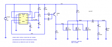
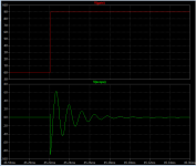
Shown below is the minimalistic "Cheapomodo V3" circuit. I honestly believe you would get equally good answers by eliminating everything to the left of M1 except Vsupply, and just driving node "GATE" with a square wave voltage source having < 20nsec rise time. Simulation results are attached; pretty close match to the real thing in the real world.
For what it's worth.
Attachments
Mark, as I mentioned it's clear that using either the QuaiModo or CheapModo jigs you can figure out the "optimum" component values. That is not in question. Instead I am wondering aloud whether or not there can be some heuristics, potentially via regression of data obtained using QM/CM, that lets a broad array of DIYers, even novices, to implement the C+RC network in their projects without having to use the QM or a scope. These people will likely be happy to use a cheap, off-the-shelf, monolithic bridge rectifier like the GBPC3510 instead of some esoteric low-capacitance, soft-recovery diodes. The diode choice could be restricted to one or two commonly available bridges. Given a particular transformer, and with the bridge known, one can determine the component values for the snubber using the QM or CM.
So let me dream out loud here a minute. What I am wondering is whether Ct and Lt have a relationship with the VA rating and secondary voltage that can be teased out by regressing data. Wouldn't it be nice, and a service to the DIY community, if such a relationship could be established? This would allow a heuristic for the choice of the C+RC components values based on some easily obtainable characteristic of the transformer.
Another way to approach this issue is to establish the upper and lower value for Rs that results in a response with say, Q<1.5 (Zeta>0.33), which gives a small overshoot and one cycle of ringing. You can repeat this for different values of Zeta away from Z=1. What you would get is a sensitivity analysis. Who knows, maybe this would show something useful, namely how close to the "best" value for Rx must you really be? If the answer is "not close" and you can get "somewhat close" via a regression analysis based heuristic, then you would really have something there. I mean it seems reasonable that if the "optimum" value is 200 Ohm, then 170 Ohm and 250 Ohm are probably "near optimum". It would be really interesting to know what the Rs sensitivity is.
So, that's all I am after. Choose a cheap monolithic bridge that is generally applicable for even large transformers, like a 35A or 50A GBPC/KBPC type. Make measurements on lots of different transformers using the QM jig. Then take a look at the data and see what can be made out of it. Is anyone game for that?
Somebody's going to have to do some work. That won't be me of course, because I am interested in inexpensive & quick ways to find the optimum snubber, and completely uninterested in procedures that result in not-optimum snubbers.
If that person decides to employ the exhaustive-enumeration-of-all-possibilities approach I outlined in post #1175, it's okay with me. If that person wants to use a different approach, it's equally okay with me. Just don't ask for my help or my blessing; I recommend to do your own work and stand behind it, yourself.
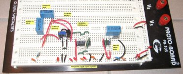
I've attached a photo of the grandfather of Quasimodo, which I slapped together on a protoboard in an hour. The optimum snubber is an hour away.
_
If that person decides to employ the exhaustive-enumeration-of-all-possibilities approach I outlined in post #1175, it's okay with me. If that person wants to use a different approach, it's equally okay with me. Just don't ask for my help or my blessing; I recommend to do your own work and stand behind it, yourself.
I've attached a photo of the grandfather of Quasimodo, which I slapped together on a protoboard in an hour. The optimum snubber is an hour away.
_
Attachments
Hmmm, well I was always intending to be "that person" and was definitely NOT insinuating that you would be saddled with it. I do have about 20 different kinds of power transformers on hand ranging from 80VA to 1kVA, and 36VCT to 124VCT. So, lots of units to test although only about half are toroidal construction.
Maybe I should put out a WANTED ad in the Swap Meet and see if I can get my hands on an already built QM jig. Otherwise I will just build one if I can get a PCB and the parts. I think it might be a fun project, and I will get to measure all of my transformers to boot.
Ahhh, "the optimum snubber is just an hour away" does have a certain ring to it, no?
- Home
- Amplifiers
- Power Supplies
- Simple, no-math transformer snubber using Quasimodo test-jig