Dx Supply performance...or Ampex supply performance...
... is awesome for an analogic supply.... linear power supply.
10 Vpp of ripple in the rectifier filters was reduced to 60 mVpp in the regulator output...this is very good
Voltage drop at 250 watts is 0.3%
See the video.... very nice... i am happy i have selected this circuit down the seventies and i am using it since that date.
https://www.youtube.com/watch?feature=player_embedded&v=tUURBkVgmqI
regards,
Carlos
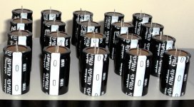
Build the Dx Supply, an Ampex vintage
linear supply tweaked by uncle charlie and used since the seventies.... 3 dozen made and some still used with Radio Amateurs...no complaints against this units ..... 41 years of reliability.
regards,
Carlos
linear supply tweaked by uncle charlie and used since the seventies.... 3 dozen made and some still used with Radio Amateurs...no complaints against this units ..... 41 years of reliability.
regards,
Carlos
Attachments

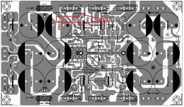
Insulator to be used in my Dx Supply, the old layout
We are preparing a better and new layout that soon gonna be published.
regards,
Carlos
Dx Supply wooden insulator, isolador de madeira para fonte Dx - YouTube
We are preparing a better and new layout that soon gonna be published.
regards,
Carlos
Dx Supply wooden insulator, isolador de madeira para fonte Dx - YouTube
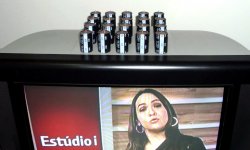
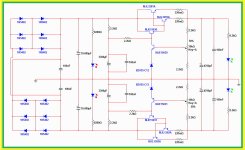
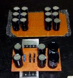
Here you have the Dx Supply image
Now it can hold the load of 2 power amplifiers, operating full power at 2 ohms loads.
But your input voltage must be 46 to 48 volts and you must adjust the output to 42 volts using proper heatsinks to the supply.
I have published long text explaining these details .
regards,
Carlos
Now it can hold the load of 2 power amplifiers, operating full power at 2 ohms loads.
But your input voltage must be 46 to 48 volts and you must adjust the output to 42 volts using proper heatsinks to the supply.
I have published long text explaining these details .
regards,
Carlos
Attachments
Last edited:
Now it can hold the load of 2 power amplifiers, operating full power at 2 ohms loads.
But your input voltage must be 46 to 48 volts and you must adjust the output to 42 volts using proper heatsinks to the supply.
I have published long text explaining these details .
regards,
Carlos
This is Great! Many Thanks Uncle Charlie.... You and Juan are the best here in DIY!
My dear Juan, Please post buttom view for hot iron in JPG. file as i have 6mm short on actual printout of your pdf file, this time i can use your layout because multi turn trimmer's are not on board, this is the parts that i cannot find in my place.
Have a nice day to both of you....
Take care,
There's a mistake in this layout that Juan have not fixed
Zimmer informed the error remain there.
Please, do not assemble the last pcboard published in thread above till i post the fixed layout.
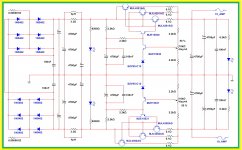
The schematic shows two output pair, in the reality we are using three, this is a matter to include on more only.
Soon we gonna have this fixed.
sorry folks!
Carlos
.........................................................................................
Capacitor diameter was a hard decision to take.... we had the need to reduce the pcboard size, in order to allow folks to use more than one supply..because of that we have decided by smaller capacitors.
I will inform layout designers..if they want to make the layout again to increase these capacitors diameter i will let them do.
Zimmer informed the error remain there.
Please, do not assemble the last pcboard published in thread above till i post the fixed layout.
The schematic shows two output pair, in the reality we are using three, this is a matter to include on more only.
Soon we gonna have this fixed.
sorry folks!
Carlos
.........................................................................................
Capacitor diameter was a hard decision to take.... we had the need to reduce the pcboard size, in order to allow folks to use more than one supply..because of that we have decided by smaller capacitors.
I will inform layout designers..if they want to make the layout again to increase these capacitors diameter i will let them do.
Last edited:
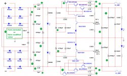
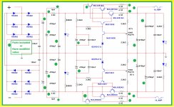
We are fixing the layout and making upgrade in the supply
Some parts are included or i have changed the value.
Coils are two layers, each layer may have 12 to 15 turns, wire is 0.5 to 1 milimeter diameter... total turns from 24 to 30 turns... resistor will be the core, as 3.3 ohms resistor, a 5 watts unit.
regards,
Carlos
Some parts are included or i have changed the value.
Coils are two layers, each layer may have 12 to 15 turns, wire is 0.5 to 1 milimeter diameter... total turns from 24 to 30 turns... resistor will be the core, as 3.3 ohms resistor, a 5 watts unit.
regards,
Carlos
Attachments
Last edited:
We are working hard..nobody sleeping here.
Soon you gonna have the layout.
Increasing width of large current tracks.
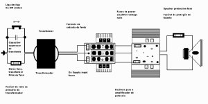
I am posting an auxiliary image to novice folks, showing an example about how to wire your amplifier, take a look at fuses, each one of them should be calculated based into your parameters....inform them to me if you want some help.
regards,
Carlos
Soon you gonna have the layout.
Increasing width of large current tracks.
I am posting an auxiliary image to novice folks, showing an example about how to wire your amplifier, take a look at fuses, each one of them should be calculated based into your parameters....inform them to me if you want some help.
regards,
Carlos
Attachments
Last edited:
There's a long text explaining fratello
Take some time to read the thread please.
33 volts AC is what we want that gonna result in 46.5 Volts DC...you will adjust the supply output to 42 volts (maximum, do not increase because Dx Super A transistors will not hold more than that...read the entire thread)
Here you have files i have promised....assemble and enjoy..this supply is great..performance is awesome.
But do not assemble in advance to read the entire thread.
regards,
Carlos
Attachments
It is a mistake man!
All layouts published about Dx Supply are defective..do not trust in anyone of them...i cannot delete them because forum does not allow us to delete wrong images after some minutes posted.
The first one made by hand, by me, is working ... was build and was tested...but was considered weak...i have made upgrade..so...there's nothing for you to build, unless you do your own layout.
We will produce new images and i will inform you the one was tested..you gonna see picture showing the pcboard assembled to prove the layout is fine.
We are having a terrible sequence of mistakes... reason why i decide that:
" no one will publish anything without prior, in advance, construction to check"
regards,
Carlos
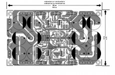
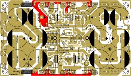
Zimmer pcboard layout
I will test hislayout:
Dx Supply - Zimmer pcboard layout - test starting - YouTube
regards,
Carlos
I will test hislayout:
Dx Supply - Zimmer pcboard layout - test starting - YouTube
regards,
Carlos
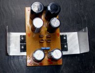
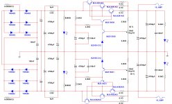
Old and new Dx Supply...the new one is bigger
In matter of fact i have increased a little (20%) the printed copy size because my capacitors are a little bit big in diameter.
The big supply will have three output pairs, and you see that we gonna have huge capacitance, including into the capacitance multiplier effect circuit.
The big one will be able to feed two channels of the Dx Super A
Volts into the series pass transistors will be 4 to 5 volts only, this way the dissipation will not be so huge as you may think.
I am just starting to build..pcboard corners cutted because needed to do this way....also the pcboard has side excess to be cutted out too...it will not be so big this way... at least 20 percent less and width will reduce a lot after trimming sides....video will explain you details soon.
I am assembling to test Zimmer layout.
regards,
Carlos
Attachments
Last edited:
Preparing Dx Supply, Zimmer layout, part two
Here you have... some videos while i am doing.
Dx Supply - Zimmer layout - start produce & test part TWO - YouTube
This is the "poor men method".. something everyone can make...obviously the better idea is to order from manufacturer or buy the stuff already made...but there's no point on that because we are DIYers... and we are inside a forum called Do it Yourself.
There are other methods, photographic method and others...this is the most simple one, the most cheap one, the easiest way, but it is not the most rational method as this produces a lot of work and takes a lot of time
Carlos
- Status
- This old topic is closed. If you want to reopen this topic, contact a moderator using the "Report Post" button.
- Home
- Amplifiers
- Power Supplies
- Dx Supply, output adjustable, stabilized power supply