True, I hadn't spotted that. Another fine theory comes crashing down!MagicBox said:looking at the sensitivity of the last two scope images they are both 200mV/Div
Just using electrolytes is not sufficient, they are too slow to supply the initial current, but a fraction after T=0 they do start to show their significance. (avoiding the L of the supply wire). No, these electrolyte buffers always need an MKT film cap of about 100nF and if you want to go for the best parallel it with a ceramic of around 100pF.
You people must not forgot that it is the audio signal that is pulling this 'instant' current through the output devices. No; it is the closed-loop HF regulation frequency that must be supplied instant current through local caps.
Yes. Totally agree! Howver, paralleling electrolytics with film is often risky, due to the possibility of forming resonant LC tanks. Each case will need to be looked at for resonance issues. That having been said, I would often like to try to add up to about 1 uF of good film, there, right at the load.
A small cap is also needed there for HF bypassing, to short-circuit high frequencies to ground, because there is a "hidden" HF feedback path through the power rail, for most transistor amp circuits.
Also, I hope everyone realizes that paralleling the electrolytics with small film caps, here, is meant to be only right at the active load device. Doing the same thing at the reservoir caps is a bad idea and can't do anything good, anyway, if there is more than about an inch or two of rail conductor before the load.
Electro's with film is not a problem, but film in parallel with film can be. Electro's ESR is too high to create issues, but the high Q of films will cause peaks if the values are wrongly picked.Yes. Totally agree! Howver, paralleling electrolytics with film is often risky, due to the possibility of forming resonant LC tanks. Each case will need to be looked at for resonance issues. That having been said, I would often like to try to add up to about 1 uF of good film, there, right at the load.
One rule of thumb is that film values very close to each, adjacent in the standard range are fine; and also if spaced by about 50 times or more. The latter is the crucial factor to keep in mind.
So:
2.2nF || 2.7nF || 3.3nF - good
2.2nF || 120nF || 1.2uF - also good
but ...
2.2nF || 10nF || 180nF - bad!!!
Frank
Originally Posted by MagicBox
I don't know if it would be neglible when talking the size of currents in a decent amp. The L could be just high enough to 'choke' the T=0 current and prohibit initial demand. I was about to put a simulation together of a full rectified supply with buffercaps and ESR simulation, along with the chopper circuit to view the transient response. I wanted to model the supply wire in there too.
The conductor self-inductance, for ANY length of conductor, WILL always prevent supplying a current at the correct time. The only question is how bad the error will be.
i doubt a 200nH inductance would have any significance
current of what size are we talking about here?
What?! 200 nH of inductance is extremely significant and should probably be the main point of much of this whole thread! That's the whole reason that the decoupling caps are so important (and the reservoir caps less so)!
Of course, if you don't mind blurred edges and a poor soundstage image, and spiky signal voltages on your rails, then don't worry about the rail inductance.
But if the goal is not high-fidelity audio reproduction, here, then why even bother discussing this at all?
Thinking only about the total reservoir capacitance will never get us there.
Inductance causes delays in current delivery, ruining the all-important transient response.
Inductance also causes time-varying currents to induce voltages across it, polluting our power and ground rails.
Even a very-small-amplitude current, if varying quickly-enough, will induce a very large voltage, across a small inductance. (The amplitude of the induced voltage does not depend on the amplitude of the time-varying current, at all, only on its rate-of-change vs time and the inductance.)
Our power supply is (or should be) all about accurately providing large, high-precision, time-varying currents, while trying to keep the voltage rails at a constant voltage. Conductor self-inductance is one of our main enemies!
The power rail conductor's inductance means that the voltage at the PSU output is NOT the same as the voltage anywhere else on the power rail, and the voltage at the ground of the PSU caps is not the same as the voltage anywhere else on the ground rails. (Those are "bad things".)
For the fastest transient signal and HF loop currents that we must be able to provide, exactly when and as demanded, anything more than about 10 to 15 nH (and often much less) means that we FAIL.
Electro's with film is not a problem, but film in parallel with film can be. Electro's ESR is too high to create issues, but the high Q of films will cause peaks if the values are wrongly picked.
One rule of thumb is that film values very close to each, adjacent in the standard range are fine; and also if spaced by about 50 times or more. The latter is the crucial factor to keep in mind.
So:
2.2nF || 2.7nF || 3.3nF - good
2.2nF || 120nF || 1.2uF - also good
but ...
2.2nF || 10nF || 180nF - bad!!!
Frank
Frank,
It has already been shown to be a problem, many times by many people. I don't feel like debating it again. See the thread on "Paralleling Film Caps with Electrolytics". Also, note that electrolytics' ESRs get very tiny at high frequencies, and they actually turn inductive instead of capacitive at high frequencies when viewed on a network analyzer, and HF is where the resonance problems occur.
The film-cap value-spacing thing looks interesting, though.
Cheers,
Tom
Last edited:
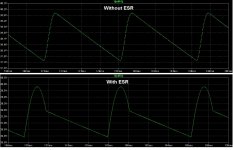
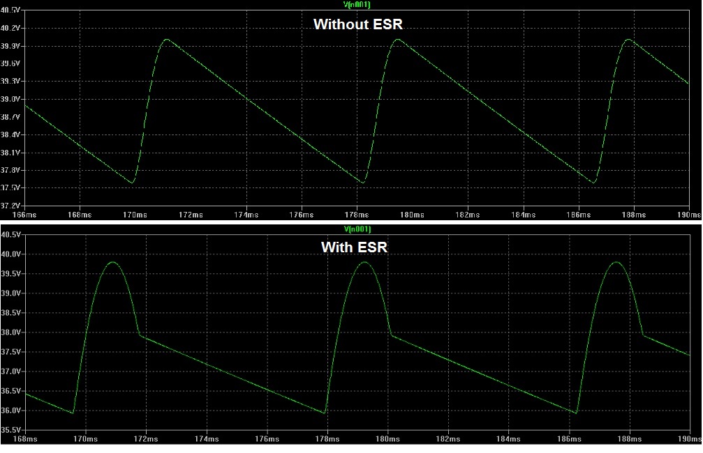
Just did a quick LTSpice simulation of a 40V linear power supply with a 14000 uF reservoir cap and an 8 Ohm load, with no ESR and with 0.1 Ohm ESR. The attached ripple voltage plot shows the effect. It's due to ESR.
Attachments
Last edited:
This with the inductance was why I designed my PCB with an El-cap+small decoupling cap right at each output device...
I have some 100V 220uF copper infused aluminium/polypropylene capacitors that I use in my speakers, could be that I should try a few of those as the final bank, they have for their size extremely low ESR as they are designed with copper-metalized end-caps and welded terminals.
I have some 100V 220uF copper infused aluminium/polypropylene capacitors that I use in my speakers, could be that I should try a few of those as the final bank, they have for their size extremely low ESR as they are designed with copper-metalized end-caps and welded terminals.
Just did a quick LTSpice simulation of a 40V linear power supply with a 14000 uF reservoir cap and an 8 Ohm load, with no ESR and with 0.1 Ohm ESR. The attached ripple voltage plot shows the effect. It's due to ESR.
Nice work !
Bit of a thread to digest, so I'll wind up my energy to chomp my way through it later on. At a quick glance, I can see that people get into trouble by ignoring the lead and connections' inductances; this will kill any benefit of bypassing, possibly make it worse, unless it's done precisely where it's needed. Rule of thumb, the smaller the cap the closer it has to be where the HF noise is the actual problem.It has already been shown to be a problem, many times by many people. I don't feel like debating it again. See the thread on "Paralleling Film Caps with Electrolytics". Also, note that electrolytics' ESRs get very tiny at high frequencies, and they actually turn inductive instead of capacitive at high frequencies when viewed on a network analyzer, and HF is where the resonance problems occur.
In general, ESR is relatively constant over the range that the cap deals with, it's the impedance that starts capacitive, momentarily becomes resistive, and then remains forever inductive, with rising frequency.
Frank
I don't know if it would be neglible when talking the size of currents in a decent amp. The L could be just high enough to 'choke' the T=0 current and prohibit initial demand. I was about to put a simulation together of a full rectified supply with buffercaps and ESR simulation, along with the chopper circuit to view the transient response. I wanted to model the supply wire in there too.
If you're using LTSpice you could save some time and download some of the ones I've already done.
Make sure that you also model the inductance in the caps, and both the ESR and ESL in the supply line, and in all of the connections if you use parallel caps. For traces or wires, most people use estimates of 1 mOhm and 25 nH per inch (1 nH per millimeter) of conductor.
If you parameterize both of those values in an LTSpice inductor, as equations based on a length parameter, it makes it easy to change the length, and then you can also do mutliple runs that automatically step through ranges of lengths, etc.
For the chopper, there are several ways to do it. One simple way is to just use a current source with pulse parameters, pulling through the output resistor. A voltage source actually works, too, since it "holds off" the power supply voltage. Or you can use an actual device, as you suggested. It's more realistic but not quite as easy to interpret the results.
I have a downloadable LTSpice model of a linear PSU that doesn't include many of the conductor parasitics, but does include a "real" transformer model (not just coupled inductors), at Spice Component and Circuit Modeling and Simulation . (There is also one there with no transformer model, which might run faster.)
You can just chop out the regulators and the soft-start circuits and probably one of the rails entirely, and add the parasitics needed.
There is another model , of just parallel caps and rails, downloadable from the post at http://www.diyaudio.com/forums/powe...lm-caps-electrolytic-caps-33.html#post2841513 .
NOTE that I accidentally used 15 nH per inch for the ESL of the conductors, which needs to be changed to 25 nH per inch, everywhere.
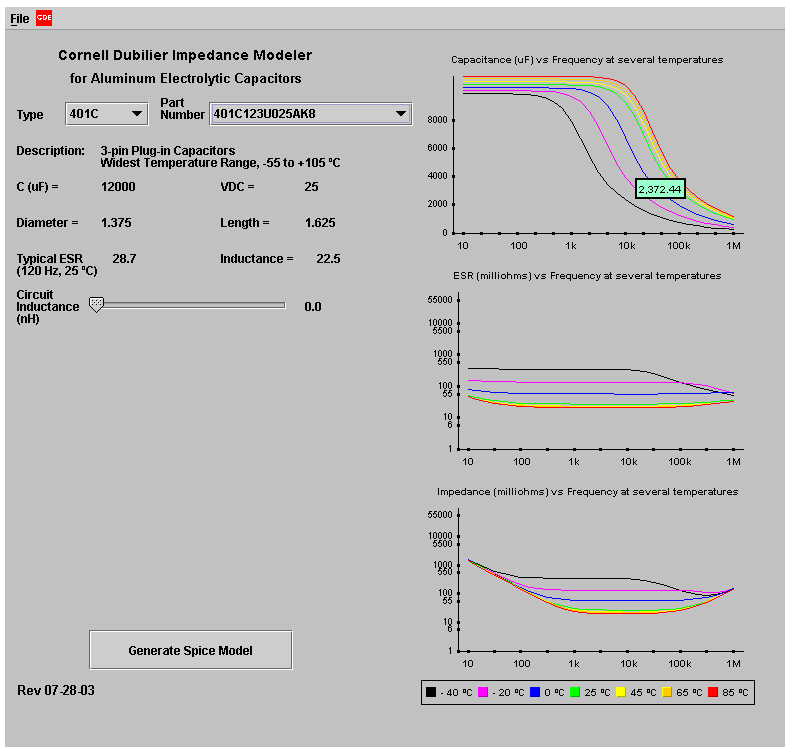
One big problem is that the ESR of electrolytic capacitors changes dramatically with frequency, which is difficult to model with LTSpice. There are equations on my psu model's scheamtic for changing the ESR for different frequencies, but it's a pain, and there's still no way to accurately model ESR for signals with wide spectral content, like fast edges. However, Cornell Dubilier does have a Java applet that automatically creates downloadable spice models for (their) electrolytic capacitors, that include the frequency and temperature dependence of the ESR! It also just plots these characteristics for you, if you're not into spice. The link is at
http://www.diyaudio.com/forums/powe...lm-caps-electrolytic-caps-11.html#post1313577
but also read through the next page or so.
That whole thread is really good but THIS is an interesting post, and is also relevant to our reservoir caps:
http://www.diyaudio.com/forums/powe...lm-caps-electrolytic-caps-38.html#post2902690
Cheers,
Tom
Bit of a thread to digest, so I'll wind up my energy to chomp my way through it later on. At a quick glance, I can see that people get into trouble by ignoring the lead and connections' inductances; this will kill any benefit of bypassing, possibly make it worse, unless it's done precisely where it's needed. Rule of thumb, the smaller the cap the closer it has to be where the HF noise is the actual problem.
In general, ESR is relatively constant over the range that the cap deals with, it's the impedance that starts capacitive, momentarily becomes resistive, and then remains forever inductive, with rising frequency.
Frank
I was going to respectfully disagree, and was going to say the following:
----------------
ESR varies directly with frequency. (It is part of the impedance, too).
DF = TAN(DELTA)@f = 2Pi*f*C*ESR(f)
The tan(delta), or DF (dissipation factor), varies by only about 100%, usually. So we can use that to estimate ESR versus frequency, with
ESR(f) = tan(delta)/(2 Pi f C)
----------------
But then I looked at:
Cornell Dubilier Electronics
which gives something like this:
http://www.diyaudio.com/forums/atta...eling-film-caps-electrolytic-caps-cdejava.jpg
And so another long-held misconception bites the dust.
Thank you. I just wish I had noticed that, years ago, before it cost me so much extra effort when doing spice modeling and simulation. (But the capacitor spice models from that CDE java applet are coool.)
Cheers,
Tom
P.S.
I'm definitely with you on the inductance issues, and also for demanded current instead of just noise, in a decoupling context.
Last edited:
")
And I've just run through some of your "vigorous" input in that thread - we are on the same page!! I've done a lot of thrashing myself using LTspice, that duplicates in many areas the sort of things you were so passionately researching. So, I know exactly why you were beating the drum about current requirements as strongly as you did, and the need to acquire full understanding of all the parasitics in the equation ...I was going to respectfully disagree, and was going to say the following:
----------------
Thank you. I just wish I had noticed that, years ago, before it cost me so much extra effort when doing spice modeling and simulation. (But the capacitor spice models from that CDE java applet are coool.)
Cheers,
Tom
P.S.
I'm definitely with you on the inductance issues, and also for demanded current instead of just noise, in a decoupling context.
Frank
Just did a quick LTSpice simulation of a 40V linear power supply with a 14000 uF reservoir cap and an 8 Ohm load, with no ESR and with 0.1 Ohm ESR. The attached ripple voltage plot shows the effect. It's due to ESR.
Thanks for this finding. It's worth more investigation.
Is it not a good way to determine the optimal value of the reservoir cap such as the peak in the waveform with ESR does not show up ?
Thanks for this finding. It's worth more investigation.
Is it not a good way to determine the optimal value of the reservoir cap such as the peak in the waveform with ESR does not show up ?
I don't think that it's a good way to determine the optimal value.
If the waveform show significant distortion due to Capacitor ESR it's time to buy a new capacitor.
It's either not a very good capacitor to start with or it has been abused and it's getting near the end of it's life.
In my experience all the reputable manufacturers' capacitors won't show that effect in a typical circuit. I have only seen that sort of waveform with poor quality electrolytic capacitors.
which gives something like this:
http://www.diyaudio.com/forums/atta...eling-film-caps-electrolytic-caps-cdejava.jpg
Thanks for the link.
I don't think that it's a good way to determine the optimal value.
If the waveform show significant distortion due to Capacitor ESR it's time to buy a new capacitor.
It's either not a very good capacitor to start with or it has been abused and it's getting near the end of it's life.
In my experience all the reputable manufacturers' capacitors won't show that effect in a typical circuit. I have only seen that sort of waveform with poor quality electrolytic capacitors.
Since ten years, I always check all the electrolytic capacitors I use with Cyril Bateman's tan-delta-meter and a capacitor meter. I am not sure many people are equipped with such an apparatus and are so methodical. I hope you are.
Among many I tested, SIC-SAFCO caps always show dependable, reliable, excellent performances.
There's at lot to learn here....capacitance falls radically with frequency, impedance rises with frequency as the caps turns inductive...hmm...This much more than I had expected. having polypropylene's/ceramic as final reservoirs seems almost mandatory..what is superb spec's worth, if there's no current to deliver.
Since ten years, I always check all the electrolytic capacitors I use with Cyril Bateman's tan-delta-meter and a capacitor meter. I am not sure many people are equipped with such an apparatus and are so methodical. I hope you are.
Among many I tested, SIC-SAFCO caps always show dependable, reliable, excellent performances.
I don't have Cyril Bateman's tan-delta-meter and I haven't been so methodical.
I was commenting on experience, OK many years ago, when only LCR electrolytic capacitors had significant ESR for a Linear simple rectified power supply though they were cheap.
The Nippon Chemi-con capacitors that were generally used had a low enough ESR that the effect on the wave form was largely absent.
- Status
- This old topic is closed. If you want to reopen this topic, contact a moderator using the "Report Post" button.
- Home
- Amplifiers
- Power Supplies
- Power Supply Resevoir Size