well here we go!
• one of the units does not have the main output connector fitted and its not in the bag. this would also have been picked up in a photo.

@AP
Can you explain?
qusp required 2 DPS-600 without the connector. please, read the posts before asking questions.
@AP
Can you explain?
@qusp: you want the connector in new package i send?
Last edited:
qusp: that one in GB (not have smps collected) near your country?
If you mean me ... I am going to collect tomorrow evening
hey Roberto, no time to answer properly, but yes please send the second connector, just so I have a set. the wire I intended to hardwire initially is 12awg stranded UPOCC and its a tiny bit too big for the holes in the PCB, I can maybe make them big enough or remove a strand or 2 to allow it to fit before soldering. I have some 12awg solid UPOCC that fits nice and snug, but it would be good to have options as the 12awg stranded fits in the connector pins nicely and its what I planned to use for power and output through the whole build. I figured it would fit, fits the amp
clocktower, please go away
I asked Roberto to not solder as an option, I was just surprised o see only one and planned to test with connectors first before final instal soldering
clocktower, please go away
I asked Roberto to not solder as an option, I was just surprised o see only one and planned to test with connectors first before final instal soldering
Last edited:
AP2 said:well, I still have the instructions for this DPS-600 for you, some important.
can you post or email this please Roberto? I plan to start testing tomorrow night.
thanks
Hi, I'm back now,sorry for delay.can you post or email this please Roberto? I plan to start testing tomorrow night.
thanks
with the resistance can try the startup condition, yes. (one res per side)
After, connecting the amplifier. not try a single resistor between + and -. This SMPS also accepts loads on one side.
DPS-600 (without bottom panel) requires a cooling surface, min. 0.8-1 ° / W. for test eg. heatsink 160mmx40x40 thickness 10mm.
the final testing done in the laboratory, determines that the startup sequence, has a duration of 500ms with 2x373mA at output (2x150R load).
The best fitting both for the heat dissipated, which for EMI, is vertically on a base panel of aluminum 3mm thickness, used as the basis of the case.In this case, we recommend installing the two DPS-600, in central position of the case. This method may help the assembly, making no visible screws on the outside bottom of the lid of the case.
Last edited:
Hi Roberto,
I picked up my dps600 last night, as commented by a few others, they are so tiny compared to the power they produce, certainly gives some options for optimised and tidy enclosure layouts.
I found this comment pretty interesting!
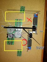
In terms of EMI, is the area marked X or O in the attached image going to have higher EMI levels?
Yellow rectangles indicate general area to be used for signal input output cables. This is my current thinking for my amp enclosure layout. 2 x The Wire LME49830 amps + 2 x The Wire - LPUHP amps (ignore LONG tx leads, just finished testing them) in one 19in enclosure.
Floor of enclosure will be 336mm x 300mm alu 2mm thick + heatsinks for LME amps at either side in area where amp pcb is sitting in photo.
I picked up my dps600 last night, as commented by a few others, they are so tiny compared to the power they produce, certainly gives some options for optimised and tidy enclosure layouts.
The best fitting both for the heat dissipated, which for EMI, is vertically on a base panel of aluminum 3mm thickness, used as the basis of the case.In this case, we recommend installing the two DPS-600, in central position of the case. This method may help the assembly, making no visible screws on the outside bottom of the lid of the case.
I found this comment pretty interesting!
In terms of EMI, is the area marked X or O in the attached image going to have higher EMI levels?
Yellow rectangles indicate general area to be used for signal input output cables. This is my current thinking for my amp enclosure layout. 2 x The Wire LME49830 amps + 2 x The Wire - LPUHP amps (ignore LONG tx leads, just finished testing them) in one 19in enclosure.
Floor of enclosure will be 336mm x 300mm alu 2mm thick + heatsinks for LME amps at either side in area where amp pcb is sitting in photo.
Attachments
My two units arrived 20 minutes before I left for work this afternoon, which gave me a good quarter of an hour to admire their splendor
Pretty certain that I'll use the Pesante Dissipante 4U 300 with the 3mm aluminium covers. My thoughts are to mount the dps-600's centrally [running front to back] with the Wire pcb's mounted one per side. Utilising an L bracket as a mount between the fets/heatsinks.
I'll start making a list of bits I need for testing & building, but it's going to be at least a month before I can make a start... I have a fixed cine-screen to buy first
Last edited:
Ahh... Just checked through the bag of bits that has been kindly supplied with the units, and am missing 1 terminal pin for the AC-in connector [eXcon 3961 3-pin housing]...
No big deal though, alternitive parts are; Molex Spox 3.96mm terminal pin - WM18821CT-ND [digikey code] & Molex Spox 3.96mm 3-pin housing - WM18814-ND
Everything else is present and correct, plus the units themselves look fantastic
No big deal though, alternitive parts are; Molex Spox 3.96mm terminal pin - WM18821CT-ND [digikey code] & Molex Spox 3.96mm 3-pin housing - WM18814-ND
Everything else is present and correct, plus the units themselves look fantastic
Hey Roberto, any comment on this mate? i'm in a very similar point of planning the layout and thus making the right length cables. in essence, does the power unit radiate more through the top or through the bottom? I would expect the top as the PCB will give some shielding. its critical for layout as I would like to get the dps600 as close as possible to the amp
Hi,
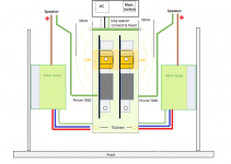
I agree with the disposition of the pic hochopeper. in case of dual mono with this SMPS, the optimal arrangement, also very beautiful, is that advice in this pic. Some customers have closed with aluminum grid, the central block. (only for aesthetics more beautiful). I have included the electromagnetic radiation (simplified). As you see, is focused around the high voltage capacitors. the remaining parts of the DPS-600, are absolutely clean. 30mm can be fitted dsp or other circuits without problems. even if someone has different needs (as hochopeper example), can certainly take note from this diagram. This diagram was used for dual mono class D also. allows a new style, compact performances not obtainable in this small space. I still have many doubts that some diy really understand how important is psu, in an amplifier eheh.
P.S. Just my opinion, why not assemble LPUP in a separate small nice case? i know some very nice at low prices.
regards
Attachments
because i'm making a multichanel dac and a multichannel amp, I dont want to be making multiple speaker cables, or multiple chassis, especially when my heatsinks and the resulting case are large enough to quite neatly have it all in one.P.S. Just my opinion, why not assemble LPUP in a separate small nice case? i know some very nice at low prices.
regards
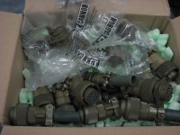
there is another reason we (hochopeper and I) are not making separate cases for the LPUHP. Its a long and arduous story; we had arranged for custom CNC chassis made to our design and we even purchased what we needed to get this to happen, but someone let us down and disappeared, so I guess we dont have the energy or desire to pay for it twice and it works out well to have them all together anyway.
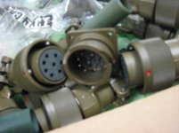
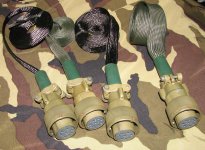
I have some very nice ITT Cannon military connectors that will make excellent multicore speaker cables.
Attachments
Hi, yes, I've mentioned something about Mr. Invisible ahah!.
Connector I know well, I have a bit of nostalgia (old memories between RF transmitters and antennas) in the old military job.eheh well, from the diagram, you know the irradiated area and have your assembly, even in some other way. for the remote control is simple to use a switch with two poles, but it is also possible to control multiple SMPS with a 1-pole switch (drawing and show notes for that matter) might be of interest to Lolo
Connector I know well, I have a bit of nostalgia (old memories between RF transmitters and antennas) in the old military job.eheh well, from the diagram, you know the irradiated area and have your assembly, even in some other way. for the remote control is simple to use a switch with two poles, but it is also possible to control multiple SMPS with a 1-pole switch (drawing and show notes for that matter) might be of interest to Lolo
i'll probably look at getting some mesh for a cage too.
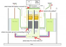
interesting speaker grounding connection suggestion, I was thinking about this too, but I dont like the idea of the positive connection being all alone. if I did it that way, I would try to position the boards so they were close and run the ground from the dps600 directly across to the amp output and twist it with the positive wire.
I know I asked you once before, but can you confirm the star ground point on the dps600 you refer to above? is it where the white line on the PCB is, or is it the middle of the 3 small standoffs under the heatsink? I have asked for clarification on a few things, noted on the image below in text
Attachments
Hi, yes, I've mentioned something about Mr. Invisible ahah!.
Connector I know well, I have a bit of nostalgia (old memories between RF transmitters and antennas) in the old military job.eheh well, from the diagram, you know the irradiated area and have your assembly, even in some other way. for the remote control is simple to use a switch with two poles, but it is also possible to control multiple SMPS with a 1-pole switch (drawing and show notes for that matter) might be of interest to Lolo
aah yes thats right ive shown you them before.
We dont like to talk about Mr Invisible
yeah I will likely be using a remotely controlled relay, probably also controllable over wifi
Thanks Roberto for that drawing, clears a few things up in my mind. Raises a few questions, qusp has asked them all already above though so I won't repeat.
Mainly clarification about the safety earth and star ground connections was where my questions were.
I was thinking about copper foil lined plastic/wooden cover for the smps, but I am honestly torn, it would mean I miss out on glimpses of these smps through the ventilation slots in the top of my chasis. Maybe just copper foil on 4 sides open at bottom for heat-sinking the smps and open at top for glimpses of these beauties! Tough choices.
Mr Invisible
PS. Forza Ferrari
Mainly clarification about the safety earth and star ground connections was where my questions were.
i'll probably look at getting some mesh for a cage too.
I was thinking about copper foil lined plastic/wooden cover for the smps, but I am honestly torn, it would mean I miss out on glimpses of these smps through the ventilation slots in the top of my chasis. Maybe just copper foil on 4 sides open at bottom for heat-sinking the smps and open at top for glimpses of these beauties! Tough choices.
Mr Invisible PS. Forza Ferrari
- Status
- This old topic is closed. If you want to reopen this topic, contact a moderator using the "Report Post" button.
- Home
- Amplifiers
- Power Supplies
- DPS-600 fast regulated smps for Wire-Amp