Hi AP2
I am still waiting for the GB smps
Arthur
Hi Arthur, Ah.. i see now your pm sorry.SMPS ready for "ups" from 2 days, you have Received notify? email by UPS.
is big holidays in Italy in this days. Received email if you have, check your name of city well, becouse "ups" sheet, did not take well.
However, tomorrow I call ups and inform you.
Last edited:
Hi Kiwik,
In general, as you said is correct. 180R resistor you can put two (one on each side to gnd) this just to turn on the DPS-600 and measure the voltage.
after that, if the wire is the first power amp, I recommend using two 22R resistors in series with the supply rails. This can help you adjust the bias and see if all is ok.
let me know how to go.
regards
thanks.
It will take a month or so before i start to assemble these amps, will test smps's at weekend
Hi AP2
I do not recieve any notice from UPS
I sent pm,please ceck data.
Hi,
At short show Datasheet complete of measure for dps-600-WA (also for D-Class version).
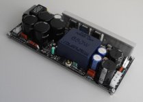
This in photo is new dps-500 (115-230Vac) 650w output availlable for Wire-Amp & D Class amplifier.
This is regulated fast response smps for audio with ultra low emission RFI/EMI without pwm.
As some already know, offers new performances in the dynamics of sound, with significant increase in the Instantaneous sound pressure, resulting in increased spl. in terms of audience, the difference is immediately noticeable on the timbre of musical instruments, especially those with steep attack, or envelope well sustain.
this smps has a voltage drop on the rail of 2.7 V under a burst of 500w audio output. impossible to obtain with transformer or other smps. these data are certain of the measures and the long research that has been done to achieve this result.
my interest is in spreading this new study on the geometry of the audio envelope, instead of wasting more time on the magician Merlin.
---------------------
regards
At short show Datasheet complete of measure for dps-600-WA (also for D-Class version).
This in photo is new dps-500 (115-230Vac) 650w output availlable for Wire-Amp & D Class amplifier.
This is regulated fast response smps for audio with ultra low emission RFI/EMI without pwm.
As some already know, offers new performances in the dynamics of sound, with significant increase in the Instantaneous sound pressure, resulting in increased spl. in terms of audience, the difference is immediately noticeable on the timbre of musical instruments, especially those with steep attack, or envelope well sustain.
this smps has a voltage drop on the rail of 2.7 V under a burst of 500w audio output. impossible to obtain with transformer or other smps. these data are certain of the measures and the long research that has been done to achieve this result.
my interest is in spreading this new study on the geometry of the audio envelope, instead of wasting more time on the magician Merlin.
---------------------
regards
Attachments
Last edited:
thanks, although I expect from you irony?..very good roberto
")
You've solved the DPS-400? I found the cause, the second protection (shortcut while work), the fault is in BAR43C, high-speed pulses exceed the threshold voltage and breaks. at this point the short circuit protection does not work anymore. I have the documentation to restore good if you want. or, send email to AudioPower support, i'm sure that change dps-400.
Regards
I wonder if any one from those who purchased the SMPS from AP, will TEST the short circuit protection function.
Because the SHORT CIRCUIT PROTECTION is not working, and I advice them to test it now before its too late for them, the SMPS units are under warranty now, and if the protection is NOT working, AP will replace it I think.
This is my advice for every one. and I hope I am wrong
And good luck for all
Power up the SMPS, then short the output, and see if it will survive
maybe in my post, it is not clear the message.I wonder if any one from those who purchased the SMPS from AP, will TEST the short circuit protection function.
Because the SHORT CIRCUIT PROTECTION is not working, and I advice them to test it now before its too late for them, the SMPS units are under warranty now, and if the protection is NOT working, AP will replace it I think.
This is my advice for every one. and I hope I am wrong
And good luck for all
Power up the SMPS, then short the output, and see if it will survive
Only in your dps-400, there may be a defect, given that the DPS-400 is equipped with good protections, including the thermal.
I asked AudioPower the list of customers who bought the DPS-400. from 2011 to the present, have been sold 790 DPS-400 with various voltages. Your only has failed.
it seems strange to me that you have not followed the way of normal service. maybe you have another goal? .. you can write bad word on AP for the next 10 years without sense.
I think you need...good luck
You have a reason for this? (all smps not have good protections) you have tested?
1) you not have sended email a company for problem on your dps-400. why?
2) what you need then?
4) without a documented reason, you can not write this..i have already warned you.
5) i want stop you, it's very simple.
1) you not have sended email a company for problem on your dps-400. why?
2) what you need then?
4) without a documented reason, you can not write this..i have already warned you.
5) i want stop you, it's very simple.
Last edited:
Roberto,
What is the max contact resistance for the remote on/off switch? I am designing for this switch to be an optically isolated solid state relay and some of them are specifying contact resistance of up to 30ohm max. Will this be an issue or will it turn on with up to 30ohm between these pins? What voltage/current spec would be appropriate for the switch? Is 150mA 60V sufficient?
Of course I could pull my DPS600 out of the box and test, but might be easier to know your answer directly
Hi,Roberto,
What is the max contact resistance for the remote on/off switch? I am designing for this switch to be an optically isolated solid state relay and some of them are specifying contact resistance of up to 30ohm max. Will this be an issue or will it turn on with up to 30ohm between these pins? What voltage/current spec would be appropriate for the switch? Is 150mA 60V sufficient?
Of course I could pull my DPS600 out of the box and test, but might be easier to know your answer directly
Remote control requires a low contact current (in the range of 20mA), so it may go well with 30R. I tested with 100R also.
the voltage on this pin is from 3V to 24V.
Last edited:
Thanks Roberto!
qusp and I are trying to think up a neat board for latching a momentary switch and driving these along with few other switches, I have only just had time to start considering the component selection recently and wanted to be sure I wasn't going to have unexpected dramas
I will post back at some point if I come up with a design that I think will be useful to others.
Cheers,
Chris
Finally gotten around to firing up the dps-600's for the first time and all with no drama
Initial setup was as suggested and everything measured as it should, so I'm one very happy camper... next will be the amp with a lower rated psu, and if all is well onto connecting up the amp & dps-600's
Paul.
Initial setup was as suggested and everything measured as it should, so I'm one very happy camper... next will be the amp with a lower rated psu, and if all is well onto connecting up the amp & dps-600's
Paul.
Moving discussion from main thread to here because this post will be mostly about DPS600 implementation.
Thanks for confirming that on the bias resistance Roberto.
Here is my idea so far:
In terms of bias levels required, we really want 3 I think ...
Or something along these lines:
Startup - 100mA
Summer bias 400mA (use this if season setting circuit has failed)
Winter bias 600mA
Which could be done with one output from a microcontroller/xbee or just a SPST toggle switch to set high/low depending on season and a few logic chips for triggering solid state relays.
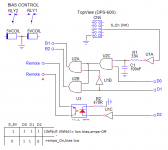
DPS600 pin connects to gnd when it hass started, so I think I can have a pull up resistor on it and run this through a buffer/inverter in the hex inverter chip I'm using for momentary switch debounce/latch circuit to trigger a relay for the DPS600 remote on switch.
This produces high for on and low for off which simplifies the logic for the bias switching.
Truth table ...
Season (1:Winter, 0:Summer)
DPS600 on status (0: OFF is open circuit, 1: ON is closed)
Season | DPS 600 | Summer | Winter | Startup
0 0 0 0 1
1 0 0 0 1
0 1 1 0 0
1 1 0 1 0
Can do this then with 2 x AND gates and 1 x inverter gate as follows:
winter is Season=High AND DPS600=High
summer is NOT(Season=High) AND DPS600=High (which should trigger every time DPS600 enable pin closes)
Hi,
This switch bias can be good for many reason.
In my opinion, it makes no sense to set 300mA-600mA, since with simple switch delay from startup. (another thing is, if you change dynamically), then I think start with 80-100, just for no stress at switch on.
High res= high current bias. (reason becouse is not good change two single res).
it's better that relay close a resistor in parallel at original. (calculate sum of res for low bias)
... notice of Opc? maybe not back from the sea?
Regards
Thanks for confirming that on the bias resistance Roberto.
Here is my idea so far:
In terms of bias levels required, we really want 3 I think ...
Or something along these lines:
Startup - 100mA
Summer bias 400mA (use this if season setting circuit has failed)
Winter bias 600mA
Which could be done with one output from a microcontroller/xbee or just a SPST toggle switch to set high/low depending on season and a few logic chips for triggering solid state relays.
DPS600 pin connects to gnd when it hass started, so I think I can have a pull up resistor on it and run this through a buffer/inverter in the hex inverter chip I'm using for momentary switch debounce/latch circuit to trigger a relay for the DPS600 remote on switch.
This produces high for on and low for off which simplifies the logic for the bias switching.
Truth table ...
Season (1:Winter, 0:Summer)
DPS600 on status (0: OFF is open circuit, 1: ON is closed)
Season | DPS 600 | Summer | Winter | Startup
0 0 0 0 1
1 0 0 0 1
0 1 1 0 0
1 1 0 1 0
Can do this then with 2 x AND gates and 1 x inverter gate as follows:
winter is Season=High AND DPS600=High
summer is NOT(Season=High) AND DPS600=High (which should trigger every time DPS600 enable pin closes)
Thanks Roberto, indeed that is quite similar to what I had in mind. A few small changes though, I will post my schematic tonight once I am at home and have time to tidy it up, I only have what I sketched out at 2am at the moment.
The one question that I do have is regarding the DPS600 enable pin. When PSU powered down is it normally high or normally floating? If it is high what voltage should I expect?
IMO CPU should default low and assert IO high as required, using NC contacts to connect extra parallel resistance for lower bias setting. This should also mean that if control power (battery) has failed then the amps will start in the lowest bias setting and stay there. Seems like the best 'failed' state possible from a controller.
Cheers,
Chris
- Status
- This old topic is closed. If you want to reopen this topic, contact a moderator using the "Report Post" button.
- Home
- Amplifiers
- Power Supplies
- DPS-600 fast regulated smps for Wire-Amp