Sy yes it is a château Cardboard ") 13.5%, but quite a drinkable one
13.5%, but quite a drinkable one
Conrad, thanks for the link! gives me some more to think about. especially interesting that the inductance of the LM317 goes down as the current goes up, explains SY's comment (in another thread) about aiming to have at least 100mA of current draw. Also of interest is that a 0.47uF cap will produce a 29Khz resonant peak I'm assuming the load was 500mA (as per the previous figure) PS I like the idea of using copper clad and using a dremel to remove material to make the circuit connections!
In my tests, input voltage is 15V out is 10V load is around 360mA (though I was testing originally at 180mA), and I DO have a 0.47uF cap (with no series resistance) in parallel with the 1000uF (that has 0r33) series resistance. Weird thing though is that the same freq noise spike is present with the scope probe disconnected and shorted..
On the tracking down noise sources, I have observed that some times are quieter than others. Most have been done at night, and all the lights in the house are compact fluorescents. I also forgot that when measuring with the scope that disconnecting the TV aerial made a big difference (we are in a unit with a common arial and amplifier for everyone), I'll have to try that again.
zigaflux, there is also a wireless router on the other side of the room, and certainly switching power supplies in the PC and also the HTPC (and probably in other components), plenty of places for noise to come from, and who knows what is in the unit upstairs .
George I might even try turning off the computer monintor and using the laptop to remote control with VNC to start and stop the measurements!
Tony.
13.5%, but quite a drinkable one Conrad, thanks for the link! gives me some more to think about. especially interesting that the inductance of the LM317 goes down as the current goes up, explains SY's comment (in another thread) about aiming to have at least 100mA of current draw. Also of interest is that a 0.47uF cap will produce a 29Khz resonant peak I'm assuming the load was 500mA (as per the previous figure) PS I like the idea of using copper clad and using a dremel to remove material to make the circuit connections!
In my tests, input voltage is 15V out is 10V load is around 360mA (though I was testing originally at 180mA), and I DO have a 0.47uF cap (with no series resistance) in parallel with the 1000uF (that has 0r33) series resistance. Weird thing though is that the same freq noise spike is present with the scope probe disconnected and shorted..
On the tracking down noise sources, I have observed that some times are quieter than others. Most have been done at night, and all the lights in the house are compact fluorescents. I also forgot that when measuring with the scope that disconnecting the TV aerial made a big difference (we are in a unit with a common arial and amplifier for everyone), I'll have to try that again.
zigaflux, there is also a wireless router on the other side of the room, and certainly switching power supplies in the PC and also the HTPC (and probably in other components), plenty of places for noise to come from, and who knows what is in the unit upstairs .
George I might even try turning off the computer monintor and using the laptop to remote control with VNC to start and stop the measurements!
Tony.
Last edited:
OK the plot thickens with respect to the 50Hz. The preamp is definitely compromising the results in the 50Hz region. Also I opened it up and checked the chip, and it would appear that I have upgraded it at some point (even though I don't recall doing so) as it has a motorola LF347N in it, which is a relatively low noise opamp with 4Mhz bandwidth, compared to the original very pedestrian, LM324 I also found I have a TL074CN from ST micro in my junk box...
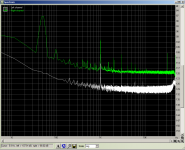
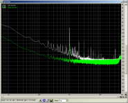
Anyway below are a series of measurements of the preamp with the scope probe switch in the ref position (shorted).
1st pic (left) no connection to sound card, (right) preamp connected 10X gain
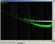
2nd pic (left) 10X gain position, right 1X gain position.
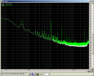
3rd pic (left) 1X gain position, right 0.1X gain position (interestingly with this one the noise is worse in the 0.1X gain position)
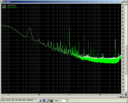
4th pic (left) 0.1X gain position, (right) 0.01X gain position.
5th pic (left) 0.01X gain position, (right) no connection to sound card.
The very interesting thing about this is that 0.1 and 0.01 gain positions just attenuate the input from the scope probe.... The opamp runs in unity gain.
I'm thinking that there may be 50Hz coming in on the shield from the sound card connection and poluting the ground connection. The preamp itself runs of a 12V gell cell Lead acid battery.
The good thing is I have plenty of bandwidth to increase the gain, the bad news is, if I increase the gain to 100X I'm going to have a big problem with the 50Hz noise.... sigh...
Tony.
Anyway below are a series of measurements of the preamp with the scope probe switch in the ref position (shorted).
1st pic (left) no connection to sound card, (right) preamp connected 10X gain
2nd pic (left) 10X gain position, right 1X gain position.
3rd pic (left) 1X gain position, right 0.1X gain position (interestingly with this one the noise is worse in the 0.1X gain position)
4th pic (left) 0.1X gain position, (right) 0.01X gain position.
5th pic (left) 0.01X gain position, (right) no connection to sound card.
The very interesting thing about this is that 0.1 and 0.01 gain positions just attenuate the input from the scope probe.... The opamp runs in unity gain.
I'm thinking that there may be 50Hz coming in on the shield from the sound card connection and poluting the ground connection. The preamp itself runs of a 12V gell cell Lead acid battery.
The good thing is I have plenty of bandwidth to increase the gain, the bad news is, if I increase the gain to 100X I'm going to have a big problem with the 50Hz noise.... sigh...
Tony.
Attachments
Last edited:
If it was a 100Hz fundamental then why is the 50 Hz dominant? Yes there will be 100Hz harmonics as a result of the 50Hz problem. Do note however that all the previous measurements were done with the on board sound card which doesn't seem to have as much of an issue at 50Hz (another reason I think the noise is coming down the shield from the input of the soundcard, to the output of the preamp.
I unfortunately forgot my comment from last night about disconnecting the TV aerial, and the soundcard preamp is in bits right now (cant see the chip without desoldering the BNC connectors). I will re-try with the TV aerial disconnected, I know I DID get some 50Hz free measurements early on, and I suspect I had disconnected the TV aerial.
Also whilst there will be some contamination of the 100Hz measurements those that show 20db or more at 100Hz have the actual 100Hz noise completely dominating any polution.
I will of course endeavour to get some clean measurements. I think whilst the preamp is in bits I might swap a few parts as well... perhaps up the 68n input cap to 100n (or possibly bigger if I have one handy). Also might up the decoupling cap to 47uF or swap it for a nichicon FG 10uF...
Also I just checked and I didn't change the voltage divider for the 2V reference when I changed the PS to 12V (from the design spec of 5V) I'n getting 4.4V instead of 2V. Will fix that too, I've got 0.66V dc on the output.......
Tony.
Yes there will be 100Hz harmonics as a result of the 50Hz problem. Do note however that all the previous measurements were done with the on board sound card which doesn't seem to have as much of an issue at 50Hz (another reason I think the noise is coming down the shield from the input of the soundcard, to the output of the preamp. I unfortunately forgot my comment from last night about disconnecting the TV aerial, and the soundcard preamp is in bits right now (cant see the chip without desoldering the BNC connectors). I will re-try with the TV aerial disconnected, I know I DID get some 50Hz free measurements early on, and I suspect I had disconnected the TV aerial.
Also whilst there will be some contamination of the 100Hz measurements those that show 20db or more at 100Hz have the actual 100Hz noise completely dominating any polution.
I will of course endeavour to get some clean measurements. I think whilst the preamp is in bits I might swap a few parts as well... perhaps up the 68n input cap to 100n (or possibly bigger if I have one handy). Also might up the decoupling cap to 47uF or swap it for a nichicon FG 10uF...
Also I just checked and I didn't change the voltage divider for the 2V reference when I changed the PS to 12V (from the design spec of 5V) I'n getting 4.4V instead of 2V. Will fix that too, I've got 0.66V dc on the output.......
Tony.
Hi George, there is already one there (though it is a low quality one). I've just run into a problem though.... I must have stuffed up the measurement of the dc on the output, I was completely not understanding what is going on there, looking at the circuit diagram again it should have had the full voltage of the divider (ie 4.4V) on the output... I changed the resistors to get the "reference 2v" and got 2V on the output... thought that was a bit odd, thought maybe it needed to be half the supply voltage (makes sense if it is a single rail the input should be half way between, if the input is half way then the output should be too! Why on earth they didn't include a dc blocking cap on the output I'm not sure, but I think I will add one in! I've potentially been feeding my sound card input with 4.4V DC, and if I change the divider to be even then 6V DC (which hasn't been connected)... I thought maybe I'd cooked the LF467N so I swapped in the TL074 and same result. I put back the original divider network and also get 4.4V on the output...
I assume if I put a few micro farads on the output all should be ok.....
Am I looking at this the right way?
Tony.
I assume if I put a few micro farads on the output all should be ok.....
Am I looking at this the right way?
Tony.
well now I'm just confused... I decided to take a measurement without the battery connected. The 50Hz is still present. If I just put an extension cable on the sound card input without the preamp plugged in there is a small amount of 50Hz but not as much.
Where it gets really weird is that if I change the gain from 10X to 1X the 50Hz gets lower.
However I just turned everything off (including the monitor) The only thing running in the vicinity is the ethernet switch, and I have a much more acceptable result.
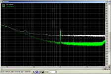
below shows comparison of 10X gain setting on preamp, compared to nothing attached to the soundcard input. scopte probe set to ref (shorted) position for the 10X measurement.
Mods I made to the preamp were:
replaced feedback caps with 47uF nichicon FG's
replaced 100uF filter cap with a rubycon YXA
replaced 10uF reference voltage cap with a 10uF nichicon FG
replaced input caps (oring 68nf wima polyester) with 100nF vishay MKP1387's
changed both resistors in the voltage divider network (for ref voltage) with 22K
added 1uF axon polyprop caps on the output (otherwise there would be 6V DC)
All this from stuff I had in my junk box,.
I don't think I'm going to completely eliminate the 50Hz problem, but I do think that this is an improvement, and If I can replicate later future results should be just that bit more "reliable"
edit: added 2nd pic to show previous 10X gain measurement compared to current. left is latest measurement
Tony.
Where it gets really weird is that if I change the gain from 10X to 1X the 50Hz gets lower.
However I just turned everything off (including the monitor) The only thing running in the vicinity is the ethernet switch, and I have a much more acceptable result.
below shows comparison of 10X gain setting on preamp, compared to nothing attached to the soundcard input. scopte probe set to ref (shorted) position for the 10X measurement.
Mods I made to the preamp were:
replaced feedback caps with 47uF nichicon FG's
replaced 100uF filter cap with a rubycon YXA
replaced 10uF reference voltage cap with a 10uF nichicon FG
replaced input caps (oring 68nf wima polyester) with 100nF vishay MKP1387's
changed both resistors in the voltage divider network (for ref voltage) with 22K
added 1uF axon polyprop caps on the output (otherwise there would be 6V DC)
All this from stuff I had in my junk box,.
I don't think I'm going to completely eliminate the 50Hz problem, but I do think that this is an improvement, and If I can replicate later future results should be just that bit more "reliable"
edit: added 2nd pic to show previous 10X gain measurement compared to current. left is latest measurement
Tony.
Attachments
Last edited:
This is why I don't like PC sound card based measurements! Whenever I do PC based stuff, I first do a reality check with something like a signal generator and a resistive divider. Once I've confirmed that the analysis gives the expected levels over the frequency range, and isn't contaminated with mystery artifacts, I have at least some confidence in what it tells me about the DUT. My experience (with an EMU-0202) is that incredibly sensitive measurements can be made, but the input circuitry is a bit weird. In my case having a DC path from the input to ground is critical to making the thing work properly. There are also so many places one can change the gain settings (and I don't know what controls what) that calibration is required every time I set it up. That said, the PC can still do measurements that are difficult or impossible with all the other test equipment on my bench. Just for fun you might try measuring the noise output of a battery. Use a fully charged SLA or a fresh alkaline. The noise level should be down at the floor of your soundcard, or darn close to it.
The noise level of an SLA can be measured if you have a 2 channel FFT which does cross-correlation. (Look for Boggs, Doak "Measurement of Voltage Noise in Chemical Batteries").
I am not Conrad's level of expertise, but have found as well that simple things like the layout of power supply wiring to the measurement amplifier can have a profound effect upon measurements! Shielded twisted pair, and a differential amplifier, short links, and a perusal of Ralph Morrison's "Grounding and Shielding Techniques in Instrumentation" are all helpful.
I keep coming back to the SSM2017 amplifier which WJ used in his 1995 TAA articles. The SSM2017 has been discontinued, and supplanted by the SSM2019 which is advertised as a 1nV/RtHz amplifier and available in DIP-8. A=100 gives the best bandwidth. I have the front end capacitor coupled with some low leakage back-to-back electrolytics, 49.9 ohm resistors to limit current inrush and clamp diodes. I had used batteries to drive the amplifier, but always forgot to turn the thing off, so now drive the amplifier with a Tektronix power supply, followed by the Pooge 5.51 rail drivers and 7805/7905 local regulators. It does better than the advertised spec!
You can always cheat, and do a "table sweep" omitting the line frequency and its harmonics.
Oh, turn off the flourescent lights too, and choose your time of day carefully -- electrical noise here in NNJ really seems to perk up between 5 and 8 in the evening.
Definitely one of the more humorous things I've read today- you're definitely far beyond me with a long history of excellent posts to prove it!I am not Conrad's level of expertise
Dual LM317 configuration
Hi,
Sorry, I not know if you develop this scheme but..does not implement anything! or explain me please.
you can implement the controller using LM317 as ref (has a good thermostabilisation), adding a NE5532 as "error amplifier" for response and filter (if necessary). a good rule not to use large capacity. working on speed, inversely to follow the undulations or loading requirements.
Regards
Roberto P.
Awpagan
Thank you for the link.
Excellent writing. I got it better by reading the whole series, starting from here:
Using 3-pin regulators off-piste: part 1
There, I found this link
Simple Voltage Regulators Part 1: Noise - [English]
which is a very good one too.
By the way, is Werner Ogiers “our” Werner?
http://www.diyaudio.com/forums/members/werner.html
Regards
George
Hi,
it is clear that works. I wanted to say that LM317 has many components inside, a very good ref voltage. makes no sense to put two. you get much more if we increase the gain by adding an op or a simple BJT, the control pin.
Regards
Roberto P.
May be this is technically correct.
And this idea (isn’t it?) is what Tony is exploiting here by taking measurements
http://www.diyaudio.com/forums/power-supplies/188975-lm317-experiments-measurements.html#post2571220
(http://www.diyaudio.com/forums/blogs/wintermute/225-yarps-yet-another-regulated-power-supply-updated-2011-02-10.html )
But any link to different –well described-approaches IHMO can always add to our knowledge and help a bit clear the mud.
Regards
George
Edit. Thanks Sy for the confirmation.
He is one of the cool-headed, knowledgable contributors in the diy community
Last edited:
Don't forget, the idea behind the 3-terminal voltage regulator is simplicity. Way back in the dark ages people built discrete regulators from the back of the old black and white RCA transistor book. Lots of parts and I'm not sure they worked all that well compared to the worst 78/79xx part. Then there was (supposedly) the LM100, the first IC regulator. I remember messing with the LM723, which they still sell today. You had to add your own output devices to get any real current. The LM317 is capable of fantastic performance, but if the circuit gets too tricky with added parts, I'd toss it and just build something else. For example, a reference zener buffered with a good low noise op-amp and self biased can be excellent (from Walt Jung's Op-amp book), and it's not hard to add an output transistor/FET for more current. You'll get better stability and (with the right parts and layout) lower noise. I have it on good authority that reference diodes selected for low noise also happen to have the best stability. BTW, with the 3-terms using double regulation absolutely improves the line regulation performance. You can also play tricks by paralleling regulators to take advantage of the statistical noise reduction.
Thanks everyone, I had a busy day today, will have to catch up tomorrow (read digest what has been posted) I did just skim the link from awpagan, and will read the whole series.
I Did one more test this morning before life got in the way checked the frequency response of the modded circuit... I think I need a bit bigger than 1uF on the output... was down 1db at 20Hz (whereas the old circuit with no output cap was only down about 0.4db at the same point)... Interesting thing though, after turning most of the eauipment I thought might be inducing the 50Hz back on, it made no difference. Perhaps the circuit mods helped somewhat, either that or me trying to clean up the ratsnest of cables at the back of the computer did...
I'll probably make the actual circuit on verro board soon, though I probably won't do too much swapping and testing once I have, but it will be nice to compare the results to the breadboard. I will redo a bunch of the tests now, checking for 50Hz pollution before doing so.
Tony.
I Did one more test this morning before life got in the way
checked the frequency response of the modded circuit... I think I need a bit bigger than 1uF on the output... was down 1db at 20Hz (whereas the old circuit with no output cap was only down about 0.4db at the same point)... Interesting thing though, after turning most of the eauipment I thought might be inducing the 50Hz back on, it made no difference. Perhaps the circuit mods helped somewhat, either that or me trying to clean up the ratsnest of cables at the back of the computer did... I'll probably make the actual circuit on verro board soon, though I probably won't do too much swapping and testing once I have, but it will be nice to compare the results to the breadboard. I will redo a bunch of the tests now, checking for 50Hz pollution before doing so.
Tony.
Hi,
it is clear that works. I wanted to say that LM317 has many components inside, a very good ref voltage. makes no sense to put two. you get much more if we increase the gain by adding an op or a simple BJT, the control pin.
Regards
Roberto P.
It makes a lot of sense.
First LM317 is working as PRE-regulator, dealing with incoming ripple and noise, making much easier job for the second LM317 to maintain regulation.
Less garbage input = less garbage output. With R1 you set current through LED (1.25V/R1). Single LED is not enough, you will need two of them.
You can still make further improvement and replace R4 with PNP like HERE
Gain for using composite regulator (dual LM317 + PNP) over single LM317 is better line rejection over wider freq range. Penallty is increased complexity and increased thermal drift due to PNP used.
Hehe I am using fred's mod as linked stormsonic! but I might have to give the second LM317 a try too, seems like an interesting option.
Well I'm even more confused after tonight I've been getting consistent measurements (around -111db for 50hz with the scope probe shorted) also put a 22uF bipolar (shock horror) on the output and it is now almost the same as the sound card for frequency response down to 10Hz.
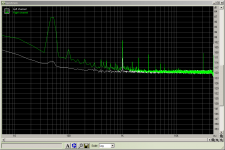
So I did a measurement of what I had previously measured... all looked good except for -88db 50Hz didn't matter what I did it wouldnt go away... This on what was previously giving around -99db at 50Hz
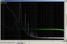
The thing that has me stumped is that I measured the input of the reg and then the output, and the reg is completely removing the 100Hz and its harmonics, and also cleaning up below 50Hz, it just seems to have this 50Hz spike, as if it is completely incapable of filtering out the 50Hz! Also the noise floor (at higher frequencies) pre reg is close to 20db lower... I guess that could be the 20db of gain in the preamp, but pre-reg also had 20db of gain...
Pic (left) reg-input (right) reg-output.
 Tony.
Tony.
but I might have to give the second LM317 a try too, seems like an interesting option. Well I'm even more confused after tonight
I've been getting consistent measurements (around -111db for 50hz with the scope probe shorted) also put a 22uF bipolar (shock horror) on the output and it is now almost the same as the sound card for frequency response down to 10Hz. So I did a measurement of what I had previously measured... all looked good except for -88db 50Hz didn't matter what I did it wouldnt go away... This on what was previously giving around -99db at 50Hz
The thing that has me stumped is that I measured the input of the reg and then the output, and the reg is completely removing the 100Hz and its harmonics, and also cleaning up below 50Hz, it just seems to have this 50Hz spike, as if it is completely incapable of filtering out the 50Hz! Also the noise floor (at higher frequencies) pre reg is close to 20db lower... I guess that could be the 20db of gain in the preamp, but pre-reg also had 20db of gain...
Pic (left) reg-input (right) reg-output.
Tony.Attachments
- Status
- This old topic is closed. If you want to reopen this topic, contact a moderator using the "Report Post" button.
- Home
- Amplifiers
- Power Supplies
- LM317 experiments and measurements