Thanks George, I was completely unaware of the effects on the bandwidth. I could add an additional toggle switch to switch to switch between the 100K and 1M resistors. I'm Mostly interested in the audio spectrum so 34Khz should be fine, and I can swap back to 10 X gain to look at the higher frequencies (up to about 86Khz with 192Khz sampling rate). My audigy only does 96Khz sampling so that tops out at about 48Khz., and I will probably be able to use the audigy with 100 X gain.
Tony.
Tony.
Hi Tony
I have some bad news and some good news for you.
I start with the bad news.
What I wrote you above are valid for TL074 but not for LM324 (which I don’t have).
But from the datasheets, one notes that:
LM324 has a unity gain bandwidth of 1MHz.
TL074 has a unity gain bandwidth of 3MHz.
This means that for the “preferred” configuration for X100 gain
C3=10uF
R5=1M
R6=10k
the LM324 will have a HF –3dB of 11.6kHz, that is 1/3 of TL074.
This is too limited a HF response.
Now the good news.
Replace your LM324 with the NE5514.
It is pin compatible and recommended in the datasheet as a replacement to LM324.
It is cheap and easy to find.
NE5514 has a unity gain bandwidth of 3MHz.
This way, you are back to the HF –3dB of 35kHz for a gain of X100 (40dB).
Regards
George
*PS
You may find other quad op amps that go higher than NE5514 (i.e. op amps that have a higher unity gain bandwidth).
But these require a very careful lay-out and power supply local decoupling, or else they will oscillate.
With the NE5514 I hope that you will not experience such oscillation problems with your existing pcb.
Last edited:
Thanks for all this George! I'd almost certainly have been disappointed if I'd taken my naive approach of simply changing the feedback resistors! in a bizarre twist my original gut feeling that the circuit might not be up to it was correct
I had a look for the NE5514 but its not at the local suppliers, TL074 is however pin compatible (even if it is jfet input compared to bipolar) will happily run at my voltage of 12V, and is abundantly available (though at rather varying prices, from about 56c to $3.50!) of course the convenient ones are $3.50 Only problem is I'm not sure if it is unity gain stable for the non 100X modes of the preamp...
Could have to put the preamp upgrade on hold for a while, and in some respects I might be better off designing something new.
I was planning on doing some more measurements tonight but its getting a bit late so will probably won't be as many as I was intending to.
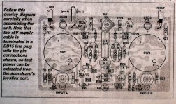
The attachment is the board layout, I don't know enough about layout to know whether it will be good/bad/indifferent for a higher bandwidth opamp.
Tony.
I had a look for the NE5514 but its not at the local suppliers, TL074 is however pin compatible (even if it is jfet input compared to bipolar) will happily run at my voltage of 12V, and is abundantly available (though at rather varying prices, from about 56c to $3.50!) of course the convenient ones are $3.50
Only problem is I'm not sure if it is unity gain stable for the non 100X modes of the preamp... Could have to put the preamp upgrade on hold for a while, and in some respects I might be better off designing something new.
I was planning on doing some more measurements tonight but its getting a bit late so will probably won't be as many as I was intending to.
The attachment is the board layout, I don't know enough about layout to know whether it will be good/bad/indifferent for a higher bandwidth opamp.
Tony.
Attachments
I had a look for the NE5514 but its not at the local suppliers
I am surprised. Have a look if they have it as SE5514. It is the same chip.
TL074 is however pin compatible (even if it is jfet input compared to bipolar) will happily run at my voltage of 12V, and is abundantly available (though at rather varying prices, from about 56c to $3.50!) of course the convenient ones are $3.50
Only problem is I'm not sure if it is unity gain stable for the non 100X modes of the preamp...
TL074 is unity gain stable. I have used it as such. Have a look at the data sheet, page 7 (and on).
http://www.datasheetcatalog.org/datasheet/texasinstruments/tl074.pdf
What I don’t know is if it can be used with single power supply in your circuit without modifications to the pcb.
If you already bought one (I hope not for $3.50, this is an arm robbery) drop it in the circuit and see how it goes.
Apply a signal at circuit’s input, load the output with ~100k (do not have your soundcard connected to it yet) and check with your oscilloscope first for presence of dc at the output. Then check for obvious asymmetric clipping when you increase the input signal. (*PS)
If none of them is present, then switch off, remove the 100k load and connect the circuit to your sound card. Pretend that nothing has changed.
The attachment is the board layout, I don't know enough about layout to know whether it will be good/bad/indifferent for a higher bandwidth opamp.
It is not OK for a high bandwidth opamps (but it will work with NE5514 and the likes)
and in some respects I might be better off designing something new.
If you’ll make certain that this circuit is not up to what you need, then yes. But do the easy (and cheap) steps first.
Regards
George
*PS. Also check for proper functioning of the LED
Last edited:
Regarding the main topic of this thread (LM317) PSU:
Have you seen this this?
(written by Eric Juaneda, poster on diyau.com)
High End Audio - LM317
Have you seen this this?
(written by Eric Juaneda, poster on diyau.com)
High End Audio - LM317
Last edited:
Tony
Now for the oscilloscope “Y out”
Some manufacturers -TEK is one of them- implement “Y out” as a buffered out signal of Input 2 channel. They pick the signal just after “Input 2 preamplifier”.
Lets call this “Case 1”
Others, implement “Y out” as a buffered out of whatever is channeled to the screen.
That can be Input 1, Input 2, Inverted Input 2, Input 1 minus Input 2, Input 1 plus Input 2 ect. They pick the signal just prior to the “Y main Amplifier”.
Lets call this “Case 2”
In all the oscilloscope schematics I’ve seen, at the pick-up point (both cases), the circuit is differential. So they use some form of “differential in to single ended out” circuit to bring out a single ended “Y out” which is specified as 50Ohm out.
The signal amplitude is 50mV per screen’s vertical division (mV/div) when the attached load is 50 Ohm, or 100mV/div open circuit.
Note here, that the maximum signal coming out the “Y out” can be much higher than simply (100mV/div) X 8 divisions. This is the case of high “Y amplification”, when only part of the waveform is visible on the screen, while the upper and the lower parts –or one of them only-are above and below the screen respectively, thus invisible.
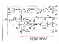
At the schematics you provided for your oscilloscope:
For “Case 1”, I would suggest pins 7 and 8 of U152 (page 48/54 of pdf) as the pick-up points for the “differential to single ended converter” circuit which will bring out the single ended “Y out” See first attachment.
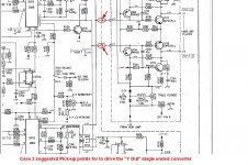
For “Case 2”, I would suggest the drive signal of the Y Output Amplifier (page 49/54 of pdf) as the pick-up points for the “differential to single ended converter” circuit. See second attachment.
Any objection or suggestion from members who have an opinion is welcome.
Tomorrow, I hope to discuss a little about the “differential to single ended converter”
Regards
George
EDIT: Actually, TEK provides a buffered Input 1 signal to "Y Out" and not Input 2 as I wrote above. My bad, sorry
Now for the oscilloscope “Y out”
Some manufacturers -TEK is one of them- implement “Y out” as a buffered out signal of Input 2 channel. They pick the signal just after “Input 2 preamplifier”.
Lets call this “Case 1”
Others, implement “Y out” as a buffered out of whatever is channeled to the screen.
That can be Input 1, Input 2, Inverted Input 2, Input 1 minus Input 2, Input 1 plus Input 2 ect. They pick the signal just prior to the “Y main Amplifier”.
Lets call this “Case 2”
In all the oscilloscope schematics I’ve seen, at the pick-up point (both cases), the circuit is differential. So they use some form of “differential in to single ended out” circuit to bring out a single ended “Y out” which is specified as 50Ohm out.
The signal amplitude is 50mV per screen’s vertical division (mV/div) when the attached load is 50 Ohm, or 100mV/div open circuit.
Note here, that the maximum signal coming out the “Y out” can be much higher than simply (100mV/div) X 8 divisions. This is the case of high “Y amplification”, when only part of the waveform is visible on the screen, while the upper and the lower parts –or one of them only-are above and below the screen respectively, thus invisible.
At the schematics you provided for your oscilloscope:
For “Case 1”, I would suggest pins 7 and 8 of U152 (page 48/54 of pdf) as the pick-up points for the “differential to single ended converter” circuit which will bring out the single ended “Y out” See first attachment.
For “Case 2”, I would suggest the drive signal of the Y Output Amplifier (page 49/54 of pdf) as the pick-up points for the “differential to single ended converter” circuit. See second attachment.
Any objection or suggestion from members who have an opinion is welcome.
Tomorrow, I hope to discuss a little about the “differential to single ended converter”
Regards
George
EDIT: Actually, TEK provides a buffered Input 1 signal to "Y Out" and not Input 2 as I wrote above. My bad, sorry
Attachments
Last edited:
Thanks for all this George!! I searched for all sorts of variations on the 5514 but nothing turned up, a google search limiting results to Australia turns up nothing as well, must be one of those odd things where a part is just not stocked in a particular region.
I haven't bought a tl074 yet, I'll sim it in ltspice to check what happens first I didn't look far enough into the datasheet to see the example with unity gain, or the fact that it generally uses a +- supply (vendor site says up to 36V or +- 18V and I assumed that meant single rail was ok.
I've seen that LM317 site before. I thought his choice of tests was a bit odd. I don't understand why he would put 22ohms in series with the output cap, (I'm using .33ohms)
I think it interestng that he thought that the best sound was with the noisiest configuration, I wonder whether the noise is "adding" what he is percieving as the qualities mentioned... I doubt that my system (or my ears) have enough resolution to detect such things I'll be happy provided I get very low hum and hiss which is my goal, these are things I do hear and that annoy me.
I should post the results showing no resistance in series with the output cap, 0r33 and 0r66 I probably should also try a panasonic FC without the resistor (as I have a 1000uF one in my junk box). Can't post results now as on the way home on the train, but maybe later tonight
Tony.
I haven't bought a tl074 yet, I'll sim it in ltspice to check what happens first
I didn't look far enough into the datasheet to see the example with unity gain, or the fact that it generally uses a +- supply (vendor site says up to 36V or +- 18V and I assumed that meant single rail was ok. I've seen that LM317 site before. I thought his choice of tests was a bit odd. I don't understand why he would put 22ohms in series with the output cap, (I'm using .33ohms)
I think it interestng that he thought that the best sound was with the noisiest configuration, I wonder whether the noise is "adding" what he is percieving as the qualities mentioned... I doubt that my system (or my ears) have enough resolution to detect such things
I'll be happy provided I get very low hum and hiss which is my goal, these are things I do hear and that annoy me. I should post the results showing no resistance in series with the output cap, 0r33 and 0r66 I probably should also try a panasonic FC without the resistor (as I have a 1000uF one in my junk box). Can't post results now as on the way home on the train, but maybe later tonight
Tony.
Last edited:
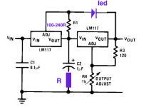
Interesting configuration Piersma! I think I'll have to sim that because I don't understand how it works.... What's the value for R? 1 ohm or less??
As promised here are a few more measurements.
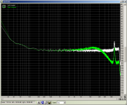
1st pic is comparison between 100uF cap on the output with 0r33 in series (left channel) and no resistor in series (right channel). Note that for some reason subsequent measurements with this cap did not get the flat noise floor and instead started to drop at higher frequencies.
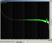
2nd pic shows 100uF output cap with 0r33 left and 0r66 right channel in series.
3rd pic is one I did last night, it is a comparison of a single 1000uF cap as post rectifier filter (left channel) vs a single 10,000uF cap post rectifier filter.
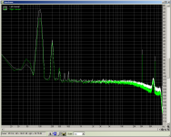
4th pic is another one I did last night for another thread, a comparison between 4.7uF adj cap and 1000uF adj cap, with only a single 1000uF cap as the filter cap. whilst there is a difference it is marginal, and I think that the CRC is a better alternative.
Tony.
As promised here are a few more measurements.
1st pic is comparison between 100uF cap on the output with 0r33 in series (left channel) and no resistor in series (right channel). Note that for some reason subsequent measurements with this cap did not get the flat noise floor and instead started to drop at higher frequencies.
2nd pic shows 100uF output cap with 0r33 left and 0r66 right channel in series.
3rd pic is one I did last night, it is a comparison of a single 1000uF cap as post rectifier filter (left channel) vs a single 10,000uF cap post rectifier filter.
4th pic is another one I did last night for another thread, a comparison between 4.7uF adj cap and 1000uF adj cap, with only a single 1000uF cap as the filter cap. whilst there is a difference it is marginal, and I think that the CRC is a better alternative.
Tony.
Attachments
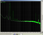
3rd pic is one I did last night, it is a comparison of a single 1000uF cap as post rectifier filter (left channel) vs a single 10,000uF cap post rectifier filter.
I love how this one objectively illustrates the high amount of noise (harmonics of 50 Hz) created by using an over-sized post-rectifier filter cap, and that it shows no reduction in noise at other frequencies. Some people think that you can never have too much capacitance in a power supply, but this clearly shows that more is not necessarily better. The effect on the audio will depend on the PSRR of the devices being powered among other things, but the supply is clearly more noisy.
p.s. I am a big fan of CRC filtering.
A little explanation is in order:Dual LM317 configuration
The configuration of the 1st 317 results in a constant voltage differential for the 2nd 317, rather than a constant voltage input. What this effectively means is that the 2nd 317 does not need to perform any line regulation (the 1st 317 takes care of that), so it only needs to control the load regulation. The result is better overall regulation at the 2nd 317 output.
(a much better explanation is at Using 3-pin regulators off-piste: part 1 on page 4).
Scrounge up a modest value Oscon cap, say 150uF/25V and try that as the output filter (if the voltage isn't too high). I think you'll see a marked improvement in noise at the higher frequencies. Big electrolytics aren't as bad as many think, but the low impedance of the Oscons can be a real eye opener.
I've used the LM317 in scientific instruments where noise was far more critical than any audio use, and IMHO if you can see much of anything with a sound card, you haven't yet extracted maximum performance from the circuit. Layout can get you, topology can get you and the specific component types can get you. BTW, it isn't available on-line, but have you seen the short app note about 3-terminal regulator noise that appears in Bob Pease's book and, I think, appeared in EDN or somewhere many years ago? It covered the fact that a regulator has much in common with an inductor, and the output circuit invariably produces a response peak with the component choices most people use?
I've used the LM317 in scientific instruments where noise was far more critical than any audio use, and IMHO if you can see much of anything with a sound card, you haven't yet extracted maximum performance from the circuit. Layout can get you, topology can get you and the specific component types can get you. BTW, it isn't available on-line, but have you seen the short app note about 3-terminal regulator noise that appears in Bob Pease's book and, I think, appeared in EDN or somewhere many years ago? It covered the fact that a regulator has much in common with an inductor, and the output circuit invariably produces a response peak with the component choices most people use?
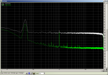
Hi Macboy, I'm not sure I'd trust the 50Hz stuff, it's been bugging me, because it comes and goes. I'm not sure its coming from the reg circuit. I just decided to give my audigy II ZS another try and in most respects the results are better than with the onboard sound card, but the 50Hz is worse... Having said that though, I do believe that the bigger cap did result in more 50Hz. I'll test again to see if I can get repeatability.
The graph shows (left) output of the reg, and (right) scope probe shorted. As you can see, most of the 50Hz is there with just the preamp and the input shorted (and the PS completely disconnected from the mains as well).
SY, the layout is hideous, have a look at post # 10 it is on breadboard and the component leads are "full length". I hope this doesn't make all the measurements worthless Also the first pic in post #7 illustrates what you are talking about perfectly! It shows the difference with just a move of the scope probe earth wire to a different point on the "same" common earth (the measurements up to that point were basically useless). I did make a post asking for feedback on my proposed layout here --> http://www.diyaudio.com/forums/power-supplies/186019-obsessing-about-layout.html but I never got any feedback BTW I'm probably going to change that after these experiments, but haven't got around to it yet. The 10,000uF's will more than likely go, and it will become 4700 3r3 4700 3r3 1000 (though I also think the third cap is largely irrelevant based on some early results I haven't posted yet.
Conrad, no I haven't seen the app note you mention, but I have simmed the effect of the output cap (especially with low esr) on the output impedance, very low esr results in significant resonance (and the bigger the cap the lower the resonance point) due to the cap forming a resonant circuit with the inherent inductance in the output of the reg.
Also although it now only goes to 48Khz (due to the audigy's 96Khz max sampling rate) , I think you will see that the problems in the higher frequencies were inadequacies in the on board sound card, rather than the noise on the circuit. Post #3 Pic #3 shows the comparison of the shorted input to the on board sound card with the reg output, again the noise is present in the sound card (or perhaps the preamp). However next order I do place I'll add in an oscon
anyway it is way past my bedtime so I'm heading off for the night. Perhaps more tomorrow
Sorry if this post is a bit incoherent, It's late, and I've had a couple of glasses of red
Tony.
The graph shows (left) output of the reg, and (right) scope probe shorted. As you can see, most of the 50Hz is there with just the preamp and the input shorted (and the PS completely disconnected from the mains as well).
SY, the layout is hideous, have a look at post # 10
it is on breadboard and the component leads are "full length". I hope this doesn't make all the measurements worthless Also the first pic in post #7 illustrates what you are talking about perfectly! It shows the difference with just a move of the scope probe earth wire to a different point on the "same" common earth (the measurements up to that point were basically useless). I did make a post asking for feedback on my proposed layout here --> http://www.diyaudio.com/forums/power-supplies/186019-obsessing-about-layout.html but I never got any feedback BTW I'm probably going to change that after these experiments, but haven't got around to it yet. The 10,000uF's will more than likely go, and it will become 4700 3r3 4700 3r3 1000 (though I also think the third cap is largely irrelevant based on some early results I haven't posted yet. Conrad, no I haven't seen the app note you mention, but I have simmed the effect of the output cap (especially with low esr) on the output impedance, very low esr results in significant resonance (and the bigger the cap the lower the resonance point) due to the cap forming a resonant circuit with the inherent inductance in the output of the reg.
Also although it now only goes to 48Khz (due to the audigy's 96Khz max sampling rate) , I think you will see that the problems in the higher frequencies were inadequacies in the on board sound card, rather than the noise on the circuit. Post #3 Pic #3 shows the comparison of the shorted input to the on board sound card with the reg output, again the noise is present in the sound card (or perhaps the preamp). However next order I do place I'll add in an oscon
anyway it is way past my bedtime so I'm heading off for the night. Perhaps more tomorrow
Sorry if this post is a bit incoherent, It's late, and I've had a couple of glasses of red
Tony.
Attachments
Last edited:
FWIW, other than some very basic things I've never been able to give useful comments on other peoples layouts. I just have to get in there and work it out myself, often confirming what I think with measurements. The appearance of the thing matters little, it's what's connected to what and where that matters. Hand wired Vector board is fine to use, but plug-in proto boards often aren't. The connections have too much resistance and it's too easy to use the busses on the sides. I'll often take a piece of plain copper-clad and cut the surface up with a burr in the Mototool to make the main pads and traces, then do sort of dead-bug construction on top. One hint- the minute you find yourself trying larger and larger caps to reduce some unwanted signal, especially low frequencies, that's a sign of a layout problem or an inherent low frequency noise problem. I have an interest in high precision references and the limiting factor in filtration is often the basic low frequency noise of the device. If there's something going on in the few Hz region, it's tough to filter it out. Random HF noise however, is a piece of cake. Another hint- don't be afraid to kill resonances with a short piece of resistance wire in series with high-Q caps. I like high-Q (low dissipation factor) caps for many reasons, but they can interact with trace inductance if you don't have some damping resistance. Last hint- don't be like me and spend lots of time looking for the mysterious HF noise, only to discover it's the CFL above the bench, or the light dimmer on the wall. 
You can read the 3-term app note here: Excerpt from Bob Pease's book
If that doesn't work, it's page 191 of Bob Pease's book, Troubleshooting Analog Circuits
You can read the 3-term app note here: Excerpt from Bob Pease's book
If that doesn't work, it's page 191 of Bob Pease's book, Troubleshooting Analog Circuits
Last edited:
Last hint- don't be like me and spend lots of time looking for the mysterious HF noise, only to discover it's the CFL above the bench, or the light dimmer on the wall.
O how true it is. Or wireless routers or switching power supplies.
- Status
- This old topic is closed. If you want to reopen this topic, contact a moderator using the "Report Post" button.
- Home
- Amplifiers
- Power Supplies
- LM317 experiments and measurements