Hes has brought up a good topic.
The 100k across the input of your pre-amp should create audible wideband noise. No separate hum component should be audible nor measurable. Develop the casing until you achieve this.
The 1k resistor should not create any audible noise nor any hum components.
The 0r0 resistor should not create any output voltage.
If you can measure the hum free difference between 0r0 and 1k0, then your system is indeed sensitive enough for what you want to do.
If you can read the (hum free) difference for 100r resistor cf. 0r0, then you have a very sensitive system.
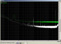
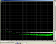
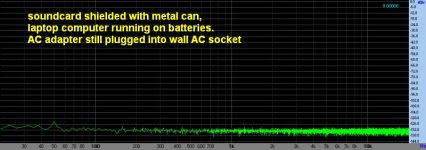
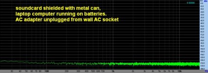
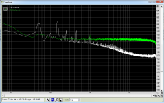
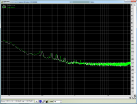
ok well the problem is certainly with the preamp itself picking up the noise. with the input to the preamp shorted I get a significant bump at 50Hz. With the output to the preamp shorted it disapears and I see the noise floor of the sound card, so it is not the cable from the preamp to the sound card that is picking up the noise.
1st pic left channel output of preamp shorted right channel no short but input shorted.
2nd pic left channel powered right channel no power, both input shorted.
So even without the preamp running it is obvious it is picking up background 50 Hz. Looks like a quality metal box is the next step required")
preamp is running off a sealed lead acid battery.
Tony.
1st pic left channel output of preamp shorted right channel no short but input shorted.
2nd pic left channel powered right channel no power, both input shorted.
So even without the preamp running it is obvious it is picking up background 50 Hz. Looks like a quality metal box is the next step required
preamp is running off a sealed lead acid battery.
Tony.
Attachments
So even without the preamp running it is obvious it is picking up background 50 Hz. Looks like a quality metal box is the next step required
preamp is running off a sealed lead acid battery.
Tony.
The box must then be grounded. From Morrison: Rule 1. An electrostatic shield enclosure, bo be effective, should be connected to the zero-signal reference potential of any circuitry contained within the shield.
Try turning off the lights, even in they're incandescents!
One of the interesting observations from Morrison's book "Grounding and Shielding" is that a room is functionally equivalent to a capacitor, and a person standing in the room influences the distribution of the eelctrostatic field.
One of the interesting observations from Morrison's book "Grounding and Shielding" is that a room is functionally equivalent to a capacitor, and a person standing in the room influences the distribution of the eelctrostatic field.
And some of us more than others- I need to go on a diet!
It's probably lesser known these days, but watch out for glass body diodes- they're light sensitive and will pick up modulation even from incandescents and impose it on the circuit!
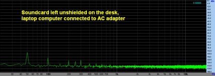
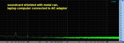
Thanks stormsonic and jackinnj! That difference just with and without the ac adaptor plugged into the wall socket is quite an eye opener!
I actually pulled the wireless card out of my pc, put the sound card at the bottom of the case and put blanking plates into all of the empty slots, This seems to have also helped somewhat (though it could be the 50 Hz wasn't as bad at the time of the tests).
I went to buy the box today but the store was closed (public holiday today) so looks like being next weekend before I can get it. I was actually thinking of putting RCA jacks on, and having them non-insulated from the case, thus making them the connection to the case and effectively having the shield continue from the cable to around the box.
The current plastic box just has a hole in it with the output lead going through and being soldered direct to the pcb. I wasn't sure whether to do the same with the BNC (input) jacks as well or not, figured I might get earth loops if I did.
Tony.
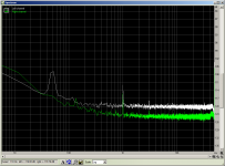
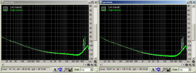
Well I think that I've made one step in the right direction I got the diecast box yesterday and the results are good. The 50 Hz problem is gone completely. RMAA graph shows left channel with input shorted (old plastic box) vs right channel input shorted new diecast box.
The is a spike at 143Hz that wasn't there before, which could possibly be some very low level oscillation due to the input and output jacks not being isolated from the box, but I think it is probably deep enough in the noise floor to be inconsequential, and it is certainly an odd enough freq to be able to be separated out. I realised that the measurement on the old box I had a 150K resistor to ground on the output, I'm going to try putting in a 56K which should give a corner freq of about 0.2Hz with the 15uF output caps, the current new box measurement has no resistor on the output.
The other thing that was interesting was how significantly the floating input performance improved!
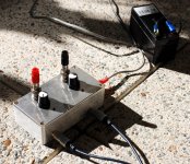
also attached a pic of the new box. The holes were a bit off (I don't have a drill press, and apparently blunt drills and not a sharp enough centre punch!) but it went together ok
It's a great day today for balcony speaker measurements so any of the PS are probably going to be delayed a little. Its not often I get a still day when everyone else is out of the house
Tony.
I got the diecast box yesterday and the results are good. The 50 Hz problem is gone completely. RMAA graph shows left channel with input shorted (old plastic box) vs right channel input shorted new diecast box. The is a spike at 143Hz that wasn't there before, which could possibly be some very low level oscillation due to the input and output jacks not being isolated from the box, but I think it is probably deep enough in the noise floor to be inconsequential, and it is certainly an odd enough freq to be able to be separated out. I realised that the measurement on the old box I had a 150K resistor to ground on the output, I'm going to try putting in a 56K which should give a corner freq of about 0.2Hz with the 15uF output caps, the current new box measurement has no resistor on the output.
The other thing that was interesting was how significantly the floating input performance improved!
also attached a pic of the new box. The holes were a bit off (I don't have a drill press, and apparently blunt drills and not a sharp enough centre punch!) but it went together ok
It's a great day today for balcony speaker measurements so any of the PS are probably going to be delayed a little. Its not often I get a still day when everyone else is out of the house
Tony.
Attachments
OK so its been a while but I finally did some more measurements I think that the metal case on the preamp gives enough shielding to get some whilst not perfect, usable results.
Note it is still on breadboard, but I think that these comparisons are worthwhile despite that.
The first pic shows that my CRT monitor was contributing to the noise. The preamp was connected to the power supply with no AC connected (ie the PS was effectively just an aerial.
Strangely I could now see 100Hz not the usual 50Hz peak. I changed the refresh rate on the monitor from 100Hz down to 90Hz and the peaks moved.
second pic shows the difference between 4V in to out voltage difference (left channel) and 5V in to out voltage difference (right channel), 4V differential was with 8.5V output voltage and 5V differential achieved by dropping the output voltage down to 8.0V output current obviously slightly lower for the second, but I think the real difference is due to the voltage drop across the reg. current in the case of 8.5V is 151mA and for 8V 142mA
Hopefully before too long I will actually build this circuit on verro board rather than the breadboard
Tony.
I think that the metal case on the preamp gives enough shielding to get some whilst not perfect, usable results. Note it is still on breadboard, but I think that these comparisons are worthwhile despite that.
The first pic shows that my CRT monitor was contributing to the noise. The preamp was connected to the power supply with no AC connected (ie the PS was effectively just an aerial.
Strangely I could now see 100Hz not the usual 50Hz peak. I changed the refresh rate on the monitor from 100Hz down to 90Hz and the peaks moved.
second pic shows the difference between 4V in to out voltage difference (left channel) and 5V in to out voltage difference (right channel), 4V differential was with 8.5V output voltage and 5V differential achieved by dropping the output voltage down to 8.0V output current obviously slightly lower for the second, but I think the real difference is due to the voltage drop across the reg. current in the case of 8.5V is 151mA and for 8V 142mA
Hopefully before too long I will actually build this circuit on verro board rather than the breadboard
Tony.
Attachments
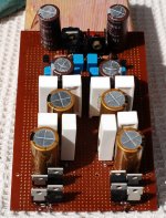
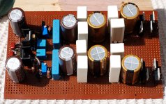
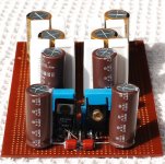
Well not too long turned out to be nearly six months But it's finally been built and I did some measurements tonight. I'm very happy with the results.
First a couple of pics of the implementation. I eneded up going with 4700, 3r3 4700 3r3, 1000uF before the reg.
The load for all the below results was only the on board load resistors which provide approx 40mA continuous load.
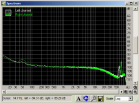
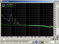
The first spectrum is taken with 1X gain on the preamp. The second is taken with the pre-amps inputs shorted, as you can see the anomylies above 40Khz are not from the PS.
The third spectrum is taken with 10X gain on the preamp, and the fourth is taken with 10X gain as well, but the right channel is post reg, and the left channel is pre reg taken at the base of the 1000uF smoothing cap. it is interesting to see how much lower the ripple is just by moving the probe down the track away from the capacitors leg. I did this to make sure that the measurements were indeed working
I was trying to get measurements using my new instrumentation amp, but I think I must have a problem with it, as I was not getting consistent results. In the end I went back to my original preamp. I set up outside with a long lead back to the computer, and my laptop running off batteries used to remote control the main computer. This seems to have worked wonders reducing the 50 Hz that has plagued the earlier measurements.
Tony.
But it's finally been built and I did some measurements tonight. I'm very happy with the results. First a couple of pics of the implementation. I eneded up going with 4700, 3r3 4700 3r3, 1000uF before the reg.
The load for all the below results was only the on board load resistors which provide approx 40mA continuous load.
The first spectrum is taken with 1X gain on the preamp. The second is taken with the pre-amps inputs shorted, as you can see the anomylies above 40Khz are not from the PS.
The third spectrum is taken with 10X gain on the preamp, and the fourth is taken with 10X gain as well, but the right channel is post reg, and the left channel is pre reg taken at the base of the 1000uF smoothing cap. it is interesting to see how much lower the ripple is just by moving the probe down the track away from the capacitors leg. I did this to make sure that the measurements were indeed working
I was trying to get measurements using my new instrumentation amp, but I think I must have a problem with it, as I was not getting consistent results. In the end I went back to my original preamp. I set up outside with a long lead back to the computer, and my laptop running off batteries used to remote control the main computer. This seems to have worked wonders reducing the 50 Hz that has plagued the earlier measurements.
Tony.
Attachments
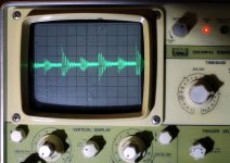
It seems I may have spoken too soon. I thought I'd get out the scope and try and get a baseline for what the actual magnitude of the pre-reg ripple was, but when I hooked it up I saw some disturbing stuff on it. after clicking through the timebase, at 5uS / div I found I had an interesting waveform. an it is quite large, at around 60mV peak to peak! and the fundamental frequency appears to be around 833Khz....
I'm not sure if it is an oscilation or something else (perhaps AM radio?). the waveform shows up before the reg as well.
anyway below is a pic. If it were AM radio though, I'd expect the waveform to be changing, but it was rock solid as shown.
Tony.
I'm not sure if it is an oscilation or something else (perhaps AM radio?). the waveform shows up before the reg as well.
anyway below is a pic. If it were AM radio though, I'd expect the waveform to be changing, but it was rock solid as shown.
Tony.
Attachments
Make sure everything in the house that could be triggering this oscillation is turned off.
CFL lamps are bad. Soldering stations are bad. HF radio transmitters are bad.
If that does not turn it off, could the repetition frequency tie in with twice the mains frequency? Diodes going into reverse bias at turn off?
CFL lamps are bad. Soldering stations are bad. HF radio transmitters are bad.
If that does not turn it off, could the repetition frequency tie in with twice the mains frequency? Diodes going into reverse bias at turn off?
Thanks Andrew, I did as you said, turned off the TV, all the lights, the printer, my amp and two computers. I went back out onto the balcony with the torch (I was measuring out there to try and get away from the interference) and low and behold the steady rather large waveform was gone!
There is still something there, but it definitely looks like AM radio, as the waveform is continually varying in amplitude, and is only about 10mV peak to peak now (the waveform looks like what you would expect to see when displaying someone's voice, except the time base is 5uS/div. My LM3886 will happily demodulate AM if I insert the rca jack only half way so I know it is around!!
I'm testing open on the bench at the moment so there is NO shielding at all, hopefully it will be fine when it goes into a proper case.
I'm curious now as to what was causing the interference. It wasn't the CFL's on the balcony or in the lounge room, as I turned them back on and it didn't come back.
I turned almost everything back on and can't reproduce the issue. The only things I didn't turn back on were the HT pc, and the other computer.
So apart from the obvious RF pick-up I think that its good
edit: it's definitely 833Khz, I set the scope to 1uS/ div and I get 12 peaks of the waveform across the 10 divisions. Still only 10mV p2p though, and it is harder to spot the amplitude modulation at that setting...
Tony.
Last edited:
Mobile phone/s and wifi and wireless networks, the door bell or the burglar alarm?
The 833kHz could be the resonant frequency within a part of the amplifier.
The trigger could be a sharp single pulse.
Can you estimate the repetition rate?
That pulse could come in via the mains or be air fed.
If it's mains fed then chassis as shield/cage will not help.
The 833kHz could be the resonant frequency within a part of the amplifier.
The trigger could be a sharp single pulse.
Can you estimate the repetition rate?
That pulse could come in via the mains or be air fed.
If it's mains fed then chassis as shield/cage will not help.
It looks like it is airborne. Apparently I am a much better antenna than the PS!! If I disconnect from the PS (and disconnect it from the mains) and simply press the scope probe into my finger I can get the same waveform at 0.4V p2p (it was 0.01V p2p on the PS). If I drop the timebase back to 10mS / division and do the same I get a 0.5V p2p 50 Hz waveform on the scope!! (a fuzzy one as the other RF is there as well).
That's rather alarming I think... How can my Body be 1/2 V different in potential to the air around it (the scope earth probe was hanging in the air).
The really weird thing though is I don't get the waveform when the probe is connected to the PS but the PS is disconnected from the mains.
Tony.
(it was 0.01V p2p on the PS). If I drop the timebase back to 10mS / division and do the same I get a 0.5V p2p 50 Hz waveform on the scope!! (a fuzzy one as the other RF is there as well). That's rather alarming I think... How can my Body be 1/2 V different in potential to the air around it (the scope earth probe was hanging in the air).
The really weird thing though is I don't get the waveform when the probe is connected to the PS but the PS is disconnected from the mains.
Tony.
That's the same problem as I have described regularly for beginners.
"I find that the quietest amplifier is the one strung out on a board with no chassis.
I have never built an amp that is quieter inside the chassis nor when it is connected to PE (The third wire in the mains cable)."
"I find that the quietest amplifier is the one strung out on a board with no chassis.
I have never built an amp that is quieter inside the chassis nor when it is connected to PE (The third wire in the mains cable)."
Yes the RF protection on input (something I do need on my LM3886 amp, but haven't gotten around to adding). In this case the input is ~18V AC (without much load) and the output is supposed to be +/- 10V DC without any extra rubbish. If it doesn't go away after being put in a case I might need to add some small ceramics on the output, though that may not even help as even with both the earth and the probe tip touching the 0V on the board (the probe tip on the actual earth alligator clip) I still got the same waveform... If I took it off the board and shorted then I got a flat line.
Tony.
Tony.
Hi Andrew, no I don't (see the post above )
But *this* is a regulated power supply, that will be used for my active crossover. The iec socket has some caps on it (The transformer is currently in a stripped PC powersupply box) I don't think I can add any RF filtering to the PS, except maybe some say 220pf caps across the first filter caps and maybe at the output? I've not seen it done before...
Tony.
) But *this* is a regulated power supply, that will be used for my active crossover. The iec socket has some caps on it (The transformer is currently in a stripped PC powersupply box) I don't think I can add any RF filtering to the PS, except maybe some say 220pf caps across the first filter caps and maybe at the output? I've not seen it done before...
Tony.
- Status
- This old topic is closed. If you want to reopen this topic, contact a moderator using the "Report Post" button.
- Home
- Amplifiers
- Power Supplies
- LM317 experiments and measurements