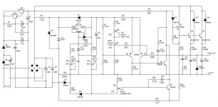
Hmmm, no one stepped up with a possible solution...? I'm deeply disappointed in you all out there in TV land. 
I went ahead and figured it out myself. It is the power supply I added to the main boards that power the pot board. I tapped off the raw supply which was a completely stupid thing to do. I swear this project is cursed!
Despite 2 regulators in series, the 5V supply for the digital pot had HUGE ripple - enough to indeed trigger the INC pin and the U/D pin on the IC - yes, that was the wiper going up and down.
Now I need to reconfigure the main board to pull the voltage from a clean source, such as the reference voltage. I will NOT be making new boards to fix this though.
And there are Members here recommending that Beginners and more experienced builders design a power amplifier with a regulated power supply !
Well, this is a bit more complex, due to the variable voltage and current limiter. Throw another wrench in the works with a digital pot, and there are bound to be details that get overlooked.
Remove the current limiter and the pot that controls the voltage output and this would be a very good regulator for an amp. Stable voltage, regardless of the load (within reason) and no significant output ripple.
Hi MJL,
I'm not suggesting your PSU could or could not drive a power amplifier.
What I am reminding other folk about is the false idea that a regulated PSU is easy and can be recommended to any power amplifier builder as an easy "Sound Quality Improver".
You are showing us that a good PSU is not at all easy to get right. You are using your skills to get it right.
It is not simple to integrate a Power Amp and Regulated PSU.
I went ahead and figured it out myself. It is the power supply I added...
No actually. I went to the considerable trouble redoing the 5V supply for this only to see absolutely no difference.
So, extreme measures:
I disconnected it from the main board altogether and ran it from a 9V battery with a 7805 reg - guess what? SAME result, that nonsense waveform at the wiper output (as seen in post #140).
Either the chip is damaged or it is somehow oscillating, even though the datasheet makes no mention of oscillation as a problem.
It is very frustrating - I could have made a very reliable mechanical coupling to a trimpot by now and be done with it.
As much as I hate giving up on something, I need to cut my losses and set aside the digital pot idea. Another example of not thoroughly prototyping something before using it.
I could have made a very reliable mechanical coupling to a trimpot by now and be done with it.
The best approach is to not make assumptions. I assumed that a multiturn pot was the only viable option for the voltage control and that assumption now turns out to be false. I have connected a regular single turn pot and it is fine - I can get the voltage adjusted very quickly and accurately.
All that hassle and frustration (and money) for something that could have been as quick and easy as the current control pot.
Live and (maybe) learn.
The fix:
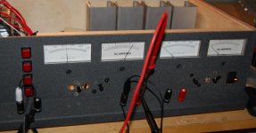
The new pots mounted for the voltage control. Unfortunately, the ideal place to put them was between the holes that the switches were in.
Photo shows supply 'A' drawing 2.2A at 35VDC and that 2.2A is the max current possible. I won't bother to show the scope at this output - you've seen that flat line before
A few minor things to do 'under the hood' and it will be done. I need to make a bezel (probably from thin hardwood) to cover the switch holes in the front panel and it will have some graduations for the voltage knobs and current limit adjust knobs.
Last edited:
You are using your skills to get it right.
More like pure bull-headed determination
What about coarse and fine adjustment of the output voltage.
Now THIS is an excellent idea! If only I had my time back, I'd have arranged the front panel to fit 2 more pots in. That would have been a better solution than a digital pot and nearly as good as a multi-turn.
I'll see if I can mount them on the 'cow catcher'
The coarse could be switched rather than continuous.
Ah, a DPDT switch to put a 10K resistor in series with the pot, either before for 'high' adjust and after for 'low' adjust.
I think I like the fine adjust pot idea better. A 1K pot will vary the voltage by about 2V over its range which would be perfect. I can get a smaller pot in the cow catcher no problem. The only obstacle is that I don't have any more 1K pots. On my next Digikey order, I get a pair and at that time I'll wire them in.
Snow is a-coming down here and it's a grand day to put some off the finishing touches on this project. Time to get it off the bench and into active duty.
I was thinking more like switch positions for 0-5Vdc, 5-10V, 10-15, 15-20, 20-25, 25-30. Would suit a 6way rotary. Then continuous fine to cover the spread of 5V at each position.
That is probably more practical for a bigger unit. The 2 pot solution will give the resolution I'd like but still make for quick adjustment. To see the accuracy of the fine adjust pot, I'd have to connect a multimeter - my analog meters will not show it precisely enough. I may, at some time in the future, change the scale on the voltage meters from 75VDC to ~37VDC for better precision.
I like multi position switches but only if they are board mounted, otherwise there are too many wires running willy nilly. There is enough of that going on now.
Snow is a-coming down here

Some additions that should have been on the PCB - resistors in series with the voltage control pots and current limit pots. I put these in place on the pots:
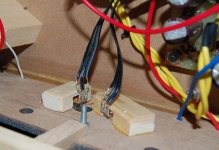
The 'light tube' that channels the light from the bulb limiter out to the front panel:
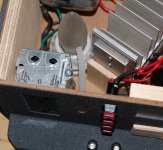
just a piece of 1/4" plastic tubing.
A look under the hood:
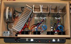
Everything in place, neat and tidy.
In place in the gear and parts hutch:
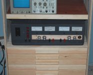
Ready for action.
A close-up of the bezel I added to the front panel:
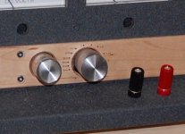
I just roughly laid out and hand printed (in pencil) the scale for the current limit.
It is done(!!) for now.
Final specs are ~0 to 35VDC at a maximum 2.2A.
A lot of fun to build, a great learning process and it looks to be a very useful tool indeed. I'm sure I'll put it to good use in many future projects.

Everything in place, neat and tidy.
In place in the gear and parts hutch:

Ready for action.
A close-up of the bezel I added to the front panel:

I just roughly laid out and hand printed (in pencil) the scale for the current limit.
It is done(!!) for now.
Final specs are ~0 to 35VDC at a maximum 2.2A.
A lot of fun to build, a great learning process and it looks to be a very useful tool indeed. I'm sure I'll put it to good use in many future projects.
I'm running it on the trial version of 11 and it isn't stable. It is running very slowly as well (a bad sign in my experience) with it taking taking 20-30 seconds to step thru .5 seconds of operation.
After I loaded it, I had to change the 2N5459 to 2SK170 (no MS model for that) and I ran it. It started to oscillate at .443 seconds and then halted at a convergence error. Maybe something was corrupted while zipping it.
This is not an overly complex circuit and that is not typical performance for MS.
Tit for tat, I'll attach mine and you can check out its performance. Give it about 20 seconds (MS timestep clock) for it to settle in. Adjust R18 for 10VDC after the LM317 and R19 for ~1.3VDC at the anode of D9.
View attachment 200413
Sorry I was out of London for a week. I am back and will try it out tomorrow-ish.
Sorry I was out of London for a week. I am back and will try it out tomorrow-ish.
Hey akis,
Did you get any further with your design?
This thread caught my attention - been wanting to do a bench supply for a while! I had more or less set myself on a discrete copy of the MC1466L with some adjustments until I looked at this.
I simulated it in LTSpice and spotted a problem. I set the output voltage for 12V (or near as possible) off load. Then I added a resistor that drew 1A. The output voltage *rose* to 12.2V. Seems a bit odd.
This circuit does have one neat advantage over the 1466L, no need for a separate floating supply. OK small transformers are cheap, but it's still a pain. However the 1466L does use high side sensing, which means it'll pick up any short, not just a short to ground.
Attachments
Last edited:
I simulated it in LTSpice and spotted a problem. I set the output voltage for 12V (or near as possible) off load. Then I added a resistor that drew 1A. The output voltage *rose* to 12.2V. Seems a bit odd.
This circuit does have one neat advantage over the 1466L, no need for a separate floating supply. OK small transformers are cheap, but it's still a pain. However the 1466L does use high side sensing, which means it'll pick up any short, not just a short to ground.
Hi jaycee,
What can I say about simulation? I use it extensively myself.
I can say that the circuit does not behave that way in Multisim and, more importantly, it does not do that in reality. The addition of a 1A load causes less than 10mV deviation in the supply voltage at 12VDC.
You might want to check the ground references for your measurements to ensure they are on the regulated side of the current sense resistor (0 volt side). This tripped me up a few times in the beginning.
I like to be efficient and run everything from one transformer. Less mains voltage wires to run, less space taken up inside the case. The implementation in this supply is in no way inferior to a separate supply and the results speak for themselves.
Not sure what you mean by 'any short, not just a short to ground'. The supply limits current on a dead short between the positive volts terminal to the 0 volts terminal to less than 2.2A. Here that is in action:
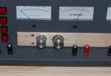
That is a 1/4 watt, 0 ohm resistor across the terminals. It looks odd but demonstrates the effectiveness of the current limit and the foldback feature.
This was actually me testing some of the new cheap resistors I bought (5000 - E12 series from 0 to 10M ohms for $20) to see how much actual current they could withstand before failing. The 0 ohm resistor didn't fail, since its wattage wasn't exceeded, despite the ~2.1A current draw (near 0 volts).
- Status
- This old topic is closed. If you want to reopen this topic, contact a moderator using the "Report Post" button.
- Home
- Amplifiers
- Power Supplies
- Lab Power Supply Design / Build
