Lies and damned lies.(or are really all circuits equally good as AndrewT has mentioned anywhere) ?
That is your misguided interpretation of something I did not post.
There are many poorly functioning or plain bad attempts at showing/building DC blockers for mains power. I have criticised a few of them when needed.
Lies and damned lies.
That is your misguided interpretation of something I did not post.
There are many poorly functioning or plain bad attempts at showing/building DC blockers for mains power. I have criticised a few of them when needed.
Such comments as this unfortunately not useful for me.
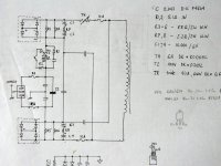
As supplement to post #80 the DC filter from Mark Levinson's ML-23 (No 23, ML23).
Attachments
Haven't seen this mentioned yet?
Circuit for correcting DC voltage component in AC supply voltage
DE 4426721 BURMESTER AUDIOSYSTEME GMBH
Circuit for correcting DC voltage component in AC supply voltage
DE 4426721 BURMESTER AUDIOSYSTEME GMBH
Attachments
because the non symetrical nature of the mains waveform changes from second to second. You can hear the transformer coming into a troubled state and going off again repeatedly, during the course of just a few minutes.
It depends very much on what other users are doing in loading the mains supply.
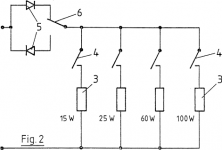
Switched resistors have no hope of matching the dozens/hundreds of other users loads on the constantly varying mains supply.
It depends very much on what other users are doing in loading the mains supply.
Switched resistors have no hope of matching the dozens/hundreds of other users loads on the constantly varying mains supply.
Who knows this DC blocker:
http://www.horch-gmbh.de/Produkte/Line Silencer.pdf
Unfortunately there is no english description available - here my try of translation of the essentials :
German:
.............
In diesem Fall schafft der HORCH Line Silencer Abhilfe! Er mißt die störende Gleichspan-
nung und neutralisiert sie. Besonderheiten des Line-Silencer hierbei sind, daß die Zeitkon-
stante des PI-Reglers auf das Driftverhalten von Transformatorkernen abgestimmt ist.
Unter Einbezug des eigenen EMV-Meßplatzes in die Entwicklung, ist es gelungen , eventuell
von dem Gerät selbst ausgehende Störungen völlig zu eleminieren. Dadurch ist gewährleistet
daß vom Line-Silencer keinerlei nachteilige Wirkung ausgehen kann!
Die Funktion des Line-Silencers wird durch Leuchtdioden angezeigt:
Gelbe LED´s : +DC / -DC: zeigt die Polarität der Gleichspannung.
Rote LED: Der Line-Silencer kompensiert aktiv.
Grüne LED : Der Gleichspannungswert ist noch so niedrig, daß keine Maßnahme erforderlich ist (ca. ±5mV).
==================================================================================
English:
.............
In this case the HORCH Line Silencer provide the appropriate solution.
It measures the unwanted DC voltage components and compensate them.
A very special feature of the Line Silencers is follow:
The time constant of the PI controller unit is adjust to the drift behavior of transformer cores (this I don't understand).
With respect of the own EMV measuring station in the concept, it has succeeded to eleminate possibility interference completely outgoing from the device itself (this I also don't understand).
This ensures, that can come from the line silencers no adverse effect!
The function of the Line Silencers is indicated by LEDs:
Yellow LED's: + DC / DC: indicates the polarity of the DC.
Red LED: The Line-compensated active silencers.
Green LED: The DC value is so low that no counterstep is necessary (approximately ± 5 mV).
Please note - since I don't even understand in German, the quality of English translation is of course questionable.
Perhaps one of the members can post a schematic of this device.
Who can post the schematic of this device ?
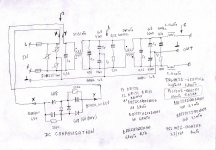
Very interesting - this kind of dc compensation I have never seen before. After redraw for better understanding this DC filter network seems to be designed for most reliable operation in order to the electrolytic caps.One more circuit of EMC filter with input DC COMPENSATION.
.
Do you find this topology in a commercial audio component or is this your own idea ?
The DC compensation is flawed !
There is no bypass around the capacitor if there is a fault current.
The capacitor will end up taking the full fault voltage (since the fault current cannot flow unimpeded) and blow up !
Far simpler to follow the ESP circuit which is based on the various (correct) posts on this Forum.
There is no bypass around the capacitor if there is a fault current.
The capacitor will end up taking the full fault voltage (since the fault current cannot flow unimpeded) and blow up !
Far simpler to follow the ESP circuit which is based on the various (correct) posts on this Forum.
.Very interesting - this kind of dc compensation I have never seen before. After redraw for better understanding this DC filter network seems to be designed for most reliable operation in order to the electrolytic caps.
Do you find this topology in a commercial audio component or is this your own idea ?
This circuit was made many times and discised in Russian forums.
Circuit works very good.
Sorry, web link has a russian characters.
.
Åù¸ ðàç î ñåòåâîì ôèëüòðå
.
Last edited:
.
This circuit was made many times and discised in Russian forums.
Circuit works very good.
Sorry, web link has a russian characters.
.
Åù¸ ðàç î ñåòåâîì ôèëüòðå
.
thank you for this URL.
by post 13 about
http_www_vegalab.ru/forum/showthread.php/19974-Ещё-раз-о-сетевом-фильтре
Åù¸ ðàç î ñåòåâîì ôèëüòðå
I read follow concerning the attached schematic (DC Filter):
Вот вариант фильтра DC, где можно поставить диодные сборки с общим катодом, которых валом на каждом рынке.
What means that?
Post 64 about
Åù¸ ðàç î ñåòåâîì ôèëüòðå - Ñòðàíèöà 4
shows an other variation again - also never seen before. In use there are bi-directionale zeners
All DC filter schemas that I have seen there you will find here in the attached files.
Attachments
http://www.power-e.ru/2007_01_82.php
.
This is interesting and useful article about EMC filter, but in Russian.
.
.
This is interesting and useful article about EMC filter, but in Russian.
.
The DC compensation is flawed !
There is no bypass around the capacitor if there is a fault current.
The capacitor will end up taking the full fault voltage (since the fault current cannot flow unimpeded) and blow up !
Far simpler to follow the ESP circuit which is based on the various (correct) posts on this Forum.
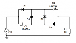
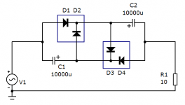
D1 and D4 (first image post #93) must be reversed, also C1 and C2 (go to the PDF by post #96).
how the formula for the calculation to get the resistor value "22R"This is corrected circuit of DC compensated.
All diodes are 6A8 (not LL4148) !
All resistors are 1 Watt.
.
Last edited:
tiefbassuebetr
.
There are two base different circuts of DC compensation, see my posts #89 and #96.
Circuit from post #89 has two pairs of diodes with common anode.
Circuit from post #96 has two pairs of diodes with common cathode VD1, VD2 and VD3, VD4, but without resistors R1 and R4 .
.
And more, there are two modifications of base circuits where two resisrors 22 Ohm added.
.
There are two base different circuts of DC compensation, see my posts #89 and #96.
Circuit from post #89 has two pairs of diodes with common anode.
Circuit from post #96 has two pairs of diodes with common cathode VD1, VD2 and VD3, VD4, but without resistors R1 and R4 .
.
And more, there are two modifications of base circuits where two resisrors 22 Ohm added.
tiefbassuebetr
.
Read this forum, but all forum is in russian.
This is Very, very interesting for you.
If you need, ask any questions about russian forum.
.
You will not see any circuits, I will send you login and password.
.
http://audioportal.su/showthread.php/25514-Сетевой-стабилизатор-AlexKorotov
.
Read this forum, but all forum is in russian.
This is Very, very interesting for you.
If you need, ask any questions about russian forum.
.
You will not see any circuits, I will send you login and password.
.
http://audioportal.su/showthread.php/25514-Сетевой-стабилизатор-AlexKorotov
Last edited:
- Home
- Amplifiers
- Power Supplies
- Variations of DC Main Filter against buzzing Toroid Transformers - what is the right?