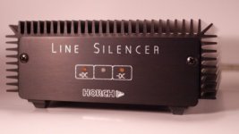
Who knows this DC blocker:
http://www.horch-gmbh.de/Produkte/Line Silencer.pdf
Unfortunately there is no english description available - here my try of translation of the essentials :
German:
.............
In diesem Fall schafft der HORCH Line Silencer Abhilfe! Er mißt die störende Gleichspan-
nung und neutralisiert sie. Besonderheiten des Line-Silencer hierbei sind, daß die Zeitkon-
stante des PI-Reglers auf das Driftverhalten von Transformatorkernen abgestimmt ist.
Unter Einbezug des eigenen EMV-Meßplatzes in die Entwicklung, ist es gelungen , eventuell
von dem Gerät selbst ausgehende Störungen völlig zu eleminieren. Dadurch ist gewährleistet
daß vom Line-Silencer keinerlei nachteilige Wirkung ausgehen kann!
Die Funktion des Line-Silencers wird durch Leuchtdioden angezeigt:
Gelbe LED´s : +DC / -DC: zeigt die Polarität der Gleichspannung.
Rote LED: Der Line-Silencer kompensiert aktiv.
Grüne LED : Der Gleichspannungswert ist noch so niedrig, daß keine Maßnahme erforderlich ist (ca. ±5mV).
==================================================================================
English:
.............
In this case the HORCH Line Silencer provide the appropriate solution.
It measures the unwanted DC voltage components and compensate them.
A very special feature of the Line Silencers is follow:
The time constant of the PI controller unit is adjust to the drift behavior of transformer cores (this I don't understand).
With respect of the own EMV measuring station in the concept, it has succeeded to eleminate possibility interference completely outgoing from the device itself (this I also don't understand).
This ensures, that can come from the line silencers no adverse effect!
The function of the Line Silencers is indicated by LEDs:
Yellow LED's: + DC / DC: indicates the polarity of the DC.
Red LED: The Line-compensated active silencers.
Green LED: The DC value is so low that no counterstep is necessary (approximately ± 5 mV).
Please note - since I don't even understand in German, the quality of English translation is of course questionable.
Perhaps one of the members can post a schematic of this device.
Attachments
Last edited:
Thanks!
Do you have without the component outlines in 1:1 for A4 scale with only the copper traces and the holes, so it's like this
Sure I could make my own board by cloning yours, but if I don't have to it would be nice
Thanks
// Olle
Do you have without the component outlines in 1:1 for A4 scale with only the copper traces and the holes, so it's like this
An externally hosted image should be here but it was not working when we last tested it.
? Or the pcb in some file format so it can be made into that through some program?Sure I could make my own board by cloning yours, but if I don't have to it would be nice
Thanks
// Olle
Last edited:
I also see this. But I haven't heard about Triacs (Triode for Alternating Current) suited for switching large torodial transformers cause its large inrush current.
Therefore I think, the type "MAC 2213A10FP" ("MAC2213A10FP") must be a new generation especially made for switch on/off of such transformers.
But where datasheets and application notes about this kind of Triacs ??
I don't find this. Only the follow weblinks about Onsemi's MAC series I have found:
MAC223-6 Datasheet pdf - TRIAC 25 AMPERE Effektivwert 200 bis 800 VOLT - Motorola
Triacs
I am still looking for informations about triacs (as a solid-state relay/power switch without the disadvantages of mechanical contacts) for switch on/off from large transformers.
Are ST's therm "ALTERNISTOR" the right choice as keyword?
http://en.wikipedia.org/wiki/TRIAC#Alternistor
http://www.datasheetcatalog.org/datasheet/stmicroelectronics/3205.pdf
Last edited:
An alternistor is specifically
designed for applications that switch highly inductive loads.
A special chip offers the same performance as two thyristors
(SCRs) wired inverse parallel (back-to-back), providing better
turn-off behavior than a standard triac. An alternistor may be triggered
from a blocking to conduction state for either polarity of
applied AC voltage with operating modes in Quadrants I, II,
and III.
This new chip construction provides two electrically separate
SCR structures, providing enhanced dv/dt characteristics while
retaining the advantages of a single-chip device.
***********************************8
Motorola had an old ap note on a solid state contactor that used a triac with a 5A relay in parallel. The triac handled the inrush current, then the relay pulled in. On turn-off the relay dropped out and then the triac was turned off. The relay negated the on voltage drop of the triac for continuous duty.
Last edited:
An alternistor is specifically
designed for applications that switch highly inductive loads.
A special chip offers the same performance as two thyristors
(SCRs) wired inverse parallel (back-to-back), providing better
turn-off behavior than a standard triac. An alternistor may be triggered
from a blocking to conduction state for either polarity of
applied AC voltage with operating modes in Quadrants I, II,
and III.
This new chip construction provides two electrically separate
SCR structures, providing enhanced dv/dt characteristics while
retaining the advantages of a single-chip device.
***********************************8
Motorola had an old ap note on a solid state contactor that used a triac with a 5A relay in parallel. The triac handled the inrush current, then the relay pulled in. On turn-off the relay dropped out and then the triac was turned off. The relay negated the on voltage drop of the triac for continuous duty.
thank you for this information (perhaps you find the number of Motorola's AN anywhere). Here some other URLs in this case:
http://highered.mcgraw-hill.com/sites/dl/free/0073106941/443736/Triac_Comm.pdf
http://www.thierry-lequeu.fr/data/AN437.pdf
http://www.irf.com/technical-info/designtp/dt94-5.pdf
http://www.nxp.com/documents/application_note/AN_3Q_TRIACS.pdf
http://www.fairchildsemi.com/an/AN/AN-3008.pdf
http://www.ece.auckland.ac.nz/archives/datasheets/motorola/moc3011.pdf
http://www.samey.is/vorur/Eurotherm/Solid202c.pdf
http://www.wrcakron.com/catalog/10b_SSR_Applications.pdf
Semiconductor relays
http://www.panasonic-electric-works.hu/pewhso/en/downloads/ds_x61_en_ssr_technical_information.pdf
http://denethor.wlu.ca/pc300/triacs/ssrtec.pdf
Do you know an URL, where are showed the switch on inrush current diagram/complex impedance character of various transformers both without and with secundary normal amplifier load and very heavy load (by use of very large whole capacity value) ??
Who knows this DC blocker:
http://www.horch-gmbh.de/Produkte/Line Silencer.pdf
Unfortunately there is no english description available - here my try of translation of the essentials :
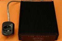
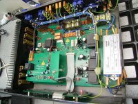
I have seen this line silencer in action at a HiFi dealer (who I trust to some extend) along with amplifiers from the same manufacturer. From what I understand it is some kind of DC servo that loads the AC line asymetrically to eliminate the DC component, presumably with resistors, hence the heatsinks. Brumester was doing something similar with their power conditioner. If nothing else it does remove transformer buzz.
Thank you for this informations. On Burmester's homepage is to read about a patent in this matter. Who knows the associated patend number ?I have seen this line silencer in action at a HiFi dealer (who I trust to some extend) along with amplifiers from the same manufacturer. From what I understand it is some kind of DC servo that loads the AC line asymetrically to eliminate the DC component, presumably with resistors, hence the heatsinks. Brumester was doing something similar with their power conditioner. If nothing else it does remove transformer buzz.
Here some URL's and an attached image from opened enclosure:
Burmester Audiosysteme GmbH ::: Produkte
Power Conditioner 948 (Heimkino, HiFi) - DigitalVD
Kunst für die Ohren: Edelschmiede für Hifi-Geräte -Video - SPIEGEL ONLINE - Nachrichten
Burmester Video-Bericht auf Spiegel Online, Allgemeines - HIFI-FORUM (Seite 2)
Attachments
Overview wanted from finished DC Blocker Units like LC
Which other suppliers there are with such dc blocker devices on PCB like
L C Audio Technology / DC Filter
and
http://www.psaudio.com/ps/products/detail/humbuster-iii ??
more threads to basic discussions:
http://forums.naimaudio.com/displayForumTopic/content/5509120095152175
http://www.diyaudio.com/forums/solid-state/37942-diy-ps-audio-humbuster.html
http://hifisound.com.ua/obzor-setevogo-filtra-ps-audio-humbuster-iii/
http://www.homecinema-fr.com/forum/viewtopic.php?f=1056&t=29803367&start=60
Last edited:
Are devices for 50A continuous flow enough (steady state or stedy state current - I don't know the english term) ?
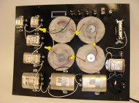
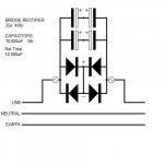
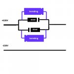
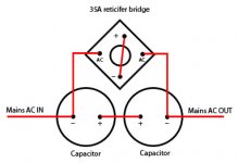
Here my circuit idea for all cases, where it is possible to insert the mains plug for the wall connection also in the other way. If there are DC >800mV, the right way for plug now is clearly find out. The proposal value of 20mF (20000 uF/100V) must be a computer grade version with lowest possible ESR (e. g. RIFA/EVOX or FTcap). Together with bypass of 100uF MKP for motor run I don't expect problems. For the diodes perhaps high speed versions with more peak current could be provide additional values of realibility.
I am looking to high power rectifier diodes, where the forward voltage drop is below 0V3 (like usual at very small signal germanium diodes) for the reverse polarity voltage of the electrolytic cap (I think, 0V3 highest reverse voltage is better for the cap than above 0V6, as usuall by normal rectifier silicon diodes. Please note: by the circuit under number 3) only one diode (namely that one for the highest reverse voltage) should have this lower value for the forward voltage drop !!!
A good solution for devices connected to the mains, that draws a constant current, i. e. the behaviour is like a constant current source (CCS).This is a method I've shown before for cleaning up AC lines!
But what happens here in case of large power amps working in Class-AB (variation of consumption power between 100W and 1000W) ??
By chance I have found the brand name "VIBEX" by various supplier, model "VR-1" (VR1), that looks interesting:Which other suppliers there are with such dc blocker devices on PCB like
L C Audio Technology / DC Filter
and
PS Audio - Humbuster III ??
http://www.acousticarts.co.uk/product_details.asp?id=610&sec=1&sub=
HIFI-Studio Wittmann: Vibex VF Linie
Vibex Reference Power Filter V1R Rhodium - die nadel - Ihr Onlineshop fuer HiFi-Zubehoer und mehr
The costs are above 1000 euros.
Only on the sites in German language there is mentioned the term "DC Filter" by the VR-1.
on their own website
:: VIBEX ::
this model isn't mentioned.
Are there a successor of this DC blocking filter?
And who knows more about the devices inside?
Last edited:
Essay's about Magnetostrictive Vibration under non-sinusoidal magnetizing condition
in the reference list (bibliography) on page 7 about
http://www.dalitech.com/Resources/Measuring Acoustic Noise Emitted by Power Transformers.pdf
I found this papers:
1) IEEE Xplore - Sign In
Who can upload this?
see also
Structure of materials: an ... - Google Bücher
and
Evaluation of Barkhausen Noise and Magnetoacoustic Emission Signals Properties for Plastically Deformed Armco Iron
Last edited:
I work in a place where there is a big lab and a lot of SMPS type work is going on. If you look at the voltage and current waverforms from all sorts of equipment connected to the mains, you see it is very distorted with lots of harmonics (think about triac dimmers, motor speed control, power supplies getting switched on and off - hopefully using FWBR!). These are some of the reasons you get DC on the mains. DC on the mains means for a period of time the positive and negative halves of the supply are not closely balanced - ie.e don't cancel out. Result is a net DC on the supply lines. Thank fully, this normally does not last for too long.
I would aldo suspect that if there is DC on the mains that it would usually be accompaied by lots of second harmonic. So here is an interesting question. We can block the DC by the diode-capacitor means we have discussed here, but that will not do anything about the second harmonic. What will the presence of the second harmonic do to the transformer? We will have an asymmetrical waveform there, with equal area on top and bottom, but different peak voltage values and correspondingly different half-cycle times.
Might it interact with core magnetic nonlinearities to re-create some DC current flow?
What will the presence of significant second harmonic do to the rectification process on the secondary side of the power transformer?
Cheers,
Bob
This is a good question. Unfortunately by the threads mentioned about
http://www.diyaudio.com/forums/soli...ry-most-interesting-comments.html#post2734158
is no answer to this (or I have overlooked an answer).
Last edited:
A good solution for devices connected to the mains, that draws a constant current, i. e. the behaviour is like a constant current source (CCS).
But what happens here in case of large power amps working in Class-AB (variation of consumption power between 100W and 1000W) ??
That variation actually makes a very small difference! The impedance of the power line is less than .3 ohms so a 900 watt change is only 2%!
The circulating currents in the filter can go above 100 amps!
That variation actually makes a very small difference! The impedance of the power line is less than .3 ohms so a 900 watt change is only 2%!
The circulating currents in the filter can go above 100 amps!
Thank you for this advice. This approach seems to be very interesting, because the goal here is not only the DC filtering. The goal by your topology is the remove from all kinds of unwanted effects from the main sinusodial curcature - i.e. transforming from non-sinusoidal to sinusoidal graph - so I think.
After start the follow thread
http://www.diyaudio.com/forums/soli...oidals-summary-most-interesting-comments.html
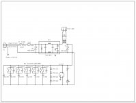
here on this forum I will collect here all jpg files of the various found circuit topologies by the there mentioned various threads to the same topic (that are not mentionned in the PDF file by my posts #1 and #33); nothing of this topologies is comparable to that one from post #73.
Now I repeat the question. Which topology of all here showed (except that one from post #73) is to be preferred for DC blocking filter (or are really all circuits equally good as AndrewT has mentioned anywhere) ?
P.S. for reading the source of each file, please log out. Then you will find that information in the file name.
Attachments
-
 DC filter Crown vs Bryston post 19 variations of DC Main Filter.gif19.8 KB · Views: 1,386
 -
 dc filter Bryston post 68 - dc blocking filter -.gif15.2 KB · Views: 1,401
 -
 DC Blocker from BMW850 - dc filter -.GIF8.2 KB · Views: 1,439
 -
 DC filter from MikeB - post 206 - dc filter -.jpg17.7 KB · Views: 754
 -
 dc filter JKoch post 57 - Variations of DC Main Filter -.gif15.2 KB · Views: 785
 -
 dc filter -only one cap- Lars clausen post 12 - Variations of DC Main Filter - .gif8.7 KB · Views: 679
 -
 dc filter -only one cap- post 91 GK - dc blocking filter.gif2.6 KB · Views: 1,571
 -
 DC Filter parallel post 78 - dc filter - preanders vs. Lars Clausen.jpg26.3 KB · Views: 633
 -
 dc filter post 201 - dc-filter -.jpg38.4 KB · Views: 682
 -
 dc filter recommend N.Pass post 68+13 - dc blocking filter -.gif2.5 KB · Views: 759
Last edited:
- Home
- Amplifiers
- Power Supplies
- Variations of DC Main Filter against buzzing Toroid Transformers - what is the right?