* I now get a funny reading when I check for a short between the + and GND points for the XMOS feed point (5V, 400ma). Black lead on GND, red lead on the +, DMM shows no continuity. However, black lead on +, red lead on GND there's a reading of 200k-300k ohms or so. The other feed point doesn't have this. Any idea how to resolve this?
After I fix those problems, I'll try out the 47uF on both feed point and sense lines again, as the earlier experiments seem to be invalid.
Disconnect the feed wires and read the regs and load points alone.
Question : how much of what I've tried out with the Zobel arrangement for the BiBs applies to the Reflektor?
The dual transistors I originally planned for are still a while out since there was a problem with the order and then there's international shipping, but I already have the pass MOSFET, and I have 48 pcs left over of the BC560C, so I can already include that for my weekend plans.
You should not terminate the Reflektor with electrolytics as an alternative. Its not like the BiB.
Disconnect the feed wires and read the regs and load points alone.
The regs read fine .... At the feed point, I'm getting a different reading now from last week ( or was it last last week? ). From GND to +, there's around .09M, and from + to GND, there's 35k ohm. This is with a benchtop Fluke 45.
On a whim, I whipped out a cheap DMM with a continuity check function and applied them across the feed points. No buzz to indicate continuity. Is that good enough, or do I still need to worry?
This is down to another circuit than the regs that I have no knowledge of. Look in its schematic to see if there is something different down the road attaching on those power receive points. A bigger cap or a branch feed that creates asymmetrical impedance readings maybe.
Well, it's been a while since I heard the system last, but it sounds like re-twisting the wire leads didn't bring back what I was looking for. Subjectively, there's a lot of oomph that's missing from the music. Just waiting for word from the designer if the readings I got were normal, otherwise I'll probably order a new board.
Quick question : any lasting effects if I ran the BiB board a lot hotter than suggested in the SSLV1.1 Calculator? Apparently, the current consumption figures provided by the designer already had headroom built in. I thought I was shunting "just" 160ma, excess current I provided was actually closer to 250ma.
In that case, the calc suggests a heatsink for the pass MOSFET with around 12.87 deg/W. What I have in there is actually around 24 deg/W. I slept through some listening sessions before, so the board was on for more than 6 hours at a time.
Should I be replacing the pass MOSFET?
No lasting problems when you run the reg hotter than you have liked for a while but it did not break. If the electrolytics did not suffer, the resistors and the semis will just go on.
Beware of placebo aural effects on first impressions also or changes elsewhere in the system.
Beware of placebo aural effects on first impressions also or changes elsewhere in the system.
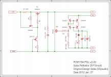
This is what Vgeorge configured at 5V for instance. (see post #6252)
What about this for R7
http://www.digikey.com/product-detail/en/MR1061K0000TAE66/MR106-1K-.01-ND/957482
MR106 is not potted I believe.Is there any advantage of using variable pot in this design?I have the George's design and the Reflektor design.One uses 10Volt and other 14 with some difference in componenents.Which one will you recommend Salas?Looks like top notch for axial and potted.
Attachments
What should be the voltage source for Reflektor in Georges design. Can I just use a Transformer 11 Volt RMS out with a bridge rectifier and capacitor bank to make 14V DC to supply Reflektor. What if the line voltage goes up (there is always a chance of 10%variation)from 120V or it drops below 120V? Will Reflektor will maintain the Voltage out?
Is there a maximum Vdc in for a given voltage out?
What is the recomended value of zobel capacitor ? I have seen 0.1 and 0.47 uf in various designs. Is there any consensus on the value? Can a Mylar cap be used i stead of a PP?
What is the significance of those resistance values in the MOSFET gate and transistor base?
I have seen two values 150 ohm and 120 ohms. How to chose their value?
Max VDC in is mainly a matter of no wasteful dissipation. That 9610 CCS Mosfet can take 200V across it.
Each one Zobel values variation had a builder or an application that was tuned by/for. All work, its a matter of their taste. If you do George's config, follow George.
Mylar can be used, prefer PP quality wise.
Gate stopper, base stopper. Anti oscillation measures, shaping the very high frequencies.
Use 150R. They are near for what they do anyway. More important is you keep them on a short lead to the semi they connect to.
Super fast replies Salas,appreciate it. My order is getting ready at digikey.
So can I use a single power source ( like a transformer with bridge rectifier and a 50,000uf capacitor bank ) to supply two or three reflektors,or does each reflektor need a separate power source for optimal performance. Is there any chance of digital noise spreading with such a config.
So can I use a single power source ( like a transformer with bridge rectifier and a 50,000uf capacitor bank ) to supply two or three reflektors,or does each reflektor need a separate power source for optimal performance. Is there any chance of digital noise spreading with such a config.
Super fast replies Salas,appreciate it. My order is getting ready at digikey.
So can I use a single power source ( like a transformer with bridge rectifier and a 50,000uf capacitor bank ) to supply two or three reflektors,or does each reflektor need a separate power source for optimal performance. Is there any chance of digital noise spreading with such a config.
I would use different transformers or at least different transformer wingdings, for a peace of mind.
Also if you have a bit higher B+, you could put an RC filter in front to drop some voltage and an additional prefiltering as a bonus. That's what I did as I used a 12VAC transformer.
- Status
- This old topic is closed. If you want to reopen this topic, contact a moderator using the "Report Post" button.
- Home
- Amplifiers
- Power Supplies
- The simplistic Salas low voltage shunt regulator