This is what I used : http://www.diyaudio.com/forums/powe...-voltage-shunt-regulator-314.html#post3791710 for my Subbu DAC.
You can use use what value capacitor you like, in a CRC arrangement before the regulator and calculate R by using Ohm' law.
You can use use what value capacitor you like, in a CRC arrangement before the regulator and calculate R by using Ohm' law.
Cant do that with the 9610 but can try with a 9640 and really good sinking. Big heat penalty if set at 2A peak and little is used up in average.
Is there any modifications needed in circuit (George's design) if 9640 is used?
I don't think so, although danger for instability may occur with any change in such wide bandwidth systems. The current should be set far higher with a much smaller control resistor of course. 9640 has much more parasitic capacitance (a price to pay with stronger silicon die) vs the 9610. So that's a change. It will also be a less effective CCS as the frequency goes higher. Mainly beyond the audio band.
Reflektor 10V
Hi,
I would like to build a Reflektor @10V and 300mA. May I know if the attached circuit is OK. Basically it's a redrawn of the original circuit at post #4287, with the following changes:
Hi,
I would like to build a Reflektor @10V and 300mA. May I know if the attached circuit is OK. Basically it's a redrawn of the original circuit at post #4287, with the following changes:
- Certain R and C values are updated, based on schematics of some later posts;
- J1 is a BF861A (Idss 3.2mA - 5.5mA) as I have some stocks, and I use R4 of 50ohm to give around 2.5mA of Id
- M2 is IRLZ24, leftovers from another project. Is this MOSFET ok?
Attachments
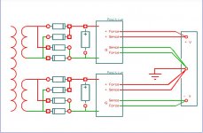
Thanks, and I have another question, is it possible to use 2 positive Reflektor to create a dual rail supply, by having separate transformer secondaries and rectifier bridges, like in the attached schematic.
I want to use this to power a Kuartlotron buffer by Keantoken.
Thanks and regards.
I want to use this to power a Kuartlotron buffer by Keantoken.
Thanks and regards.
Attachments
When stacking same polarities to dual its like when stacking batteries. Arrange the Kelvin wiring like in the attached drawing. You may use more LEDS and smaller trimmer value to have the best part of the 10Vout made up by active parts.
Attachments
Ok I made the Reflektor from parts on a vero board but for sure did not do something right. No voltage out put. How to trouble shoot?I am feeding with 20VDC and using Georges circuit with resistors R2,R3,R6 150Ohm and R1 0.82 Ohm. I am getting 20V between IRF9610's drain and Ground.
Trace it out carefully against the original circuit. BTW, there is an open connection between the two Leds in that drawing from George, that is some print glitch, it should be connected.
If all is well with the wiring, then you will look for dead semis that do not show VBE or VGS voltages or dead LEDs. Or bad orientations, check pinouts.
If all is well with the wiring, then you will look for dead semis that do not show VBE or VGS voltages or dead LEDs. Or bad orientations, check pinouts.
- Status
- This old topic is closed. If you want to reopen this topic, contact a moderator using the "Report Post" button.
- Home
- Amplifiers
- Power Supplies
- The simplistic Salas low voltage shunt regulator