what do you need to do to modify the reflector for 3.3V out?
You take the red LED out and you bridge its position. If Vout won't be 3.3V exactly (matter of various manufacture LEDs VF characteristics), and 3.1-3.2V is unacceptable by the client circuit, you may use a small value resistor in its place to add the missing 0.XV. 120R maybe.
You take the red LED out and you bridge its position. If Vout won't be 3.3V exactly (matter of various manufacture LEDs VF characteristics), and 3.1-3.2V is unacceptable by the client circuit, you may use a small value resistor in its place to add the missing 0.XV. 120R maybe.
Do you think an 1.7v LED will do it. What is the calculation to use to see what amount of voltage drop you need?
if v drop is higher is it suppose to sound better? i built 1.1 with 9610, 9540 and the heat is unmanageable (with the inadequate sinks that i haven't bought the replacement for) when input v is 5v higher than the output. with less than 2v drop, i can use dinky to220 heatsinks and still have the best sound i have heard.
You risk inadequate CCS current stability and higher IRF9610 parasitic capacitance especially when mains can go lower with such little drop margin but the shunt voltage part of the regulator can still work when Vin is very close to Vout, as much or closer than the best LDO reg chips. If the load ain't much steady in consumption it could partially modulate the CCS having it behave like a ballast resistor. Which you may hear or you may not given the specific application.
P.S. Is it the one in this DAC config? If yes, is the load's current draw rather steady? How high a CCS setting in mA?
An externally hosted image should be here but it was not working when we last tested it.
You risk inadequate CCS current stability and higher IRF9610 parasitic capacitance especially when mains can go lower with such little drop margin but the shunt voltage part of the regulator can still work when Vin is very close to Vout, as much or closer than the best LDO reg chips. If the load ain't much steady in consumption it could partially modulate the CCS having it behave like a ballast resistor. Which you may hear or you may not given the specific application.
The CCS can behave like a ballast resistor only if the voltage drop across the regulator is too low and the load swings too far?
If the voltage across the regulator is high enough, then there can be no current limiting, correct?
what is the most updated schematic for higher voltage versions, 12/15V.I do not want to dig through more than 640 pages.
Use the same you got, just more LEDS.
The CCS can behave like a ballast resistor only if the voltage drop across the regulator is too low and the load swings too far?
If the voltage across the regulator is high enough, then there can be no current limiting, correct?
When Vdrop>5V the CCS will behave more robustly.
(2VBE+VF)+((VgsM2/1k)*Rextra)). Measure the LEDs VF at ~2mA state, or in circuit.
Salas can you please explain what all those abbreviations represents? I have some ideas but let me hear it from horses mouth.

Two times VBE is the total drop of the two transistors in the Vref side mirror's leg.
VgsM2 is the VBE equivalent in the output MOSFET (drop between gate and source pins).
1K is R7. Rextra is any small resistor you may need in series with D1 to add a bit of voltage when your LED's forward voltage drop (VF) will be short to the target.
VgsM2 is the VBE equivalent in the output MOSFET (drop between gate and source pins).
1K is R7. Rextra is any small resistor you may need in series with D1 to add a bit of voltage when your LED's forward voltage drop (VF) will be short to the target.
Abbreviations:
Vbe voltage from base to emitter of a BJT transistor
Vgs voltage from gate to source of a FET transistor
Vf voltage across a passing diode (Vf stands for forward voltage)
Rextra describes itself. The resistance across an extra resistor
mA milli Ampere = Ampere/1000
LED light emitting diode
M2 the transistor identifier on the schematic
1k one kilo ohm = ohms*1000
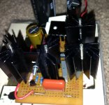
Thank you guys, my salas reflektor is up and running. I will change my tranny to a 9V one soon. Till then have to run with 7.4ohm 5W resistor also working as a CRC filter. It might be all in my head but there is a positive difference when I changed my Smsps wallwart that pwered my active USB hub ,which is needed for my HRT streamer pro to run in asynchronous mode with Squeezebox touch.
Congrats. You put on the larger sinks already?
Yes I used the second one from the one asked before,got from digikey yesterday.
Attachments
Hi Salas
Can you tell me which parts of Reflektor affect subjective performance?
Im refering to the schematic on post 6263
http://www.diyaudio.com/forums/powe...-voltage-shunt-regulator-627.html#post3791710
Can you tell me which parts of Reflektor affect subjective performance?
Im refering to the schematic on post 6263
http://www.diyaudio.com/forums/powe...-voltage-shunt-regulator-627.html#post3791710
- Status
- This old topic is closed. If you want to reopen this topic, contact a moderator using the "Report Post" button.
- Home
- Amplifiers
- Power Supplies
- The simplistic Salas low voltage shunt regulator