measure your GRs and find out which ones are at which end of the tolerance range.
You may find that some are pretty close to BLs.
Select the current of each FET to suit the location it is in.
They all do a different job and as a result they can all pass a different current.
You may find that some are pretty close to BLs.
Select the current of each FET to suit the location it is in.
They all do a different job and as a result they can all pass a different current.
jkeny said:Is 170BL needed in these regulators or will 170GR do?
I ask because of the difficulty of obtaining 170BLs & I have 170GRs already!
GRs towards 5mA IDSS are fine both for low pinch off and for stiffening the Zener enough.
jkeny said:Thanks Andrew & I'm sorry if I'm being lazy or dumb but is there a schematic with the currents shown at the Fets?
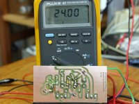
jkeny, the current through the jfets is generally dependent both on the voltage across them (drain/source pins) and also, when gate and source connected together, to the device itself (Idss). But in the salas regulator the voltage across is large enough for each jfet location that it is the Idss of the device itself that will set the current through it. Therefore, measure your jfets, easily done this way: connect the gate and drain (pins 2 and 3) together to the positive lead of your digital multimeter set on 20mA range. The common (black) lead of the DMM to - 9V (battery), and pin 1 of the jfet (drain) to + 9V. Do not hold the jfet in your hand, as Idss is very temperature dependent. Then wait for a bit until the current shown stabilizes. That's your Idss, and that's about the value that you can expect to have in the circuit. Choose the higher current GRs for your circuit.
Simplistic Regulator LV PCB
It seems there's a limit to the actual number of pixels to be uploaded...
Anyway, the file can be had here. It's a 1200dpi drawing, three of them fit in a regular eurocard format (10x16cm).
The backside along with its components.
It seems there's a limit to the actual number of pixels to be uploaded...
Anyway, the file can be had here. It's a 1200dpi drawing, three of them fit in a regular eurocard format (10x16cm).
The backside along with its components.
Attachments
Salas said:Looks nice. For what you gonna use it for? I guess that every pcb drawing must be shown, it will surely suit someone. Upload it I vote.
Thank you Salas (and for your intellectual work on the circuit of cause). It's going to power the playback and recording amplifiers of one of my tape decks. Keeping the bits and bytes out

You mentioned pink noise from the zener. Will the small tantalum caps be beneficial for filtering noise? No problems encountered regarding stability here.
Nicoch: Vgeorge have used Hammond chokes, about 1H, as passive Pi prefilters. You can chose something with enough DCR so to drop volts. He reported a small gain in smoothness subjectively. I use a a wirewound resistor of proper Wattage before the main filter capacitor, if I want to drop some excessive voltage. And its a mild filter as well. Don't wrap a shunt in a series reg, it defies the principle IMO.
Disco: Very cool work. You can use a 1000uF cap across the Vref instead of 100uF if the particular Zeners are a bit noisy, which I rather doubt bcs 12V Zeners usually are even better than Leds. Yes, the Zener noise is ''pinkier'' in spectrum. Droops. Nobody had stability problems with V1 in practice. Avoid small tants IMO. Less stuff is for the better. Only when you listen, drop us a few lines here to know if you could detect any subjective upgrade to your sound.
Disco: Very cool work. You can use a 1000uF cap across the Vref instead of 100uF if the particular Zeners are a bit noisy, which I rather doubt bcs 12V Zeners usually are even better than Leds. Yes, the Zener noise is ''pinkier'' in spectrum. Droops. Nobody had stability problems with V1 in practice. Avoid small tants IMO. Less stuff is for the better. Only when you listen, drop us a few lines here to know if you could detect any subjective upgrade to your sound.
that's only 12V between input and output.nicoch46 said:Vin 57v Vout 44,8v 100ma
How much will the supply voltage drop when you draw the 100mA current plus the other currents to run the regulator and CCS?
How much will the raw Vin ripple when you draw that maximum current?
How much will the Vin drop when mains voltage is running at minimum supply tolerance?
If you subtract all of these from Vin, you still need >4V drop through the CCS to get effective regulation from the circuit.
I thanks Sala,s fine with passive , but coils only on phono for my driver stage I will do with R , 10r or 5r 10w ?
-Andrew
the salas design is for 53vin 44Vout with 100ma ccs
with 100ccs(x4) I have (40Vac trafo ) 57vdc at input of shunt and Vout 44,8
the 230v is rock stable
for my driver stage I will do with R , 10r or 5r 10w ? -Andrew
the salas design is for 53vin 44Vout with 100ma ccs
with 100ccs(x4) I have (40Vac trafo ) 57vdc at input of shunt and Vout 44,8
the 230v is rock stable
- Status
- This old topic is closed. If you want to reopen this topic, contact a moderator using the "Report Post" button.
- Home
- Amplifiers
- Power Supplies
- The simplistic Salas low voltage shunt regulator