Tham said:There is going to be a slight problem with the pending comparison...my v1 is residing in the B1 now (permanently) while the v2 is powering a phono stage. Looks like I have an excuse to build another v1 again to compare.
Fortunately it is a very easy circuit to build. Thanks for doing this! Any further input will be immensely helpful for others that might be thinking of building either circuit. In my opinion one cannot go wrong with either version.
I am slowly rebuilding my lm3886 little amp which I plan to regulate via v2, whenever I get a bit of time off from a DHT headphone amp that I'm trying to design.
These are the best sounding IMO...nicoch46 said:IR HFA08PB60
... and either the BYW29s or perhaps the 08ETH06s.
I know it's probably just imagination, but there does seem to be a slight difference between all of them with the same setup (no other supply changes)
I do know that they don't like getting at all hot, and I screw them down to free air heatsinks, and not the warm/hot chassis.
hope this may be of assistance_
Good evening fellow DIY-ers,
Enjoyed reading your adventures with the Simplistic designs and descided I had to build a set myself
I had a go with the Kitsch Reg, but stumbled on a peculiar output voltage of only 13,4V. Waiting for the 2SK170bl to arrive I used 2SK170gr instead. Maybe this is the cause of the low output as these JFETs test in the range 3 to 5mA.
Can someone confirm this to be the cause or must I look for a mistake elsewhere?
Some measurements:
* input voltage is 30Vdc ;
* output voltage is set for 24V by two zeners of 12V in series ;
* total current consumption is about 280mA ;
* voltage over R3 (10 ohm) = 0,037V so 3,7mA is flowing through the zener ;
* voltage over the 2 series 12V zeners is only 13,0V.
Best regards from Holland,
Jaap
Welcome to the discussion Jaap. Can you point to the schematic you've implemented please?
disco said:Good evening fellow DIY-ers,
Enjoyed reading your adventures with the Simplistic designs and descided I had to build a set myself
I had a go with the Kitsch Reg, but stumbled on a peculiar output voltage of only 13,4V. Waiting for the 2SK170bl to arrive I used 2SK170gr instead. Maybe this is the cause of the low output as these JFETs test in the range 3 to 5mA.
Can someone confirm this to be the cause or must I look for a mistake elsewhere?
Some measurements:
* input voltage is 30Vdc ;
* output voltage is set for 24V by two zeners of 12V in series ;
* total current consumption is about 280mA ;
* voltage over R3 (10 ohm) = 0,037V so 3,7mA is flowing through the zener ;
* voltage over the 2 series 12V zeners is only 13,0V.
Best regards from Holland,
Jaap
The load is a 7W 470 ohm resistor.
Raising the input voltage to 33V makes no difference BTW.
Measurements taken at 30V input:
over the LEDS is 6.0V ;
the Base of Q3 is at 0.52V ;
the Collector of Q3 is at 9,4V ;
R1 is raised to 7.2 ohm.
Maybe it's wise to have another look for cold joints tomorrow.
Raising the input voltage to 33V makes no difference BTW.
Measurements taken at 30V input:
over the LEDS is 6.0V ;
the Base of Q3 is at 0.52V ;
the Collector of Q3 is at 9,4V ;
R1 is raised to 7.2 ohm.
Maybe it's wise to have another look for cold joints tomorrow.
170GR is doing better than BL under the Zener. Gives lower Vgs (OFF). Not a problem. Since your leds are 2V strong, use 15R R1 BTW.
As the Zeners are giving 13V ref, its very normal that you get 13.4V out. It works, only the Vref is wrong. Maybe there is something wrong with the Zener part numbers or their health, or you tap off between them to the BC550 base by mistake? First thing to do is to get a 24V Zener and substitute.
As the Zeners are giving 13V ref, its very normal that you get 13.4V out. It works, only the Vref is wrong. Maybe there is something wrong with the Zener part numbers or their health, or you tap off between them to the BC550 base by mistake? First thing to do is to get a 24V Zener and substitute.
don't use series Zeners, unless you can ensure that both dissipate >5% of their rating and preferably ~10% of their rating.
It is far better to use a 400mW single Zener and calculate the minimum current required to dissipate ~10% of maximum allowable.
Check the current through r3.
It is far better to use a 400mW single Zener and calculate the minimum current required to dissipate ~10% of maximum allowable.
Check the current through r3.
Hi guys, thanks for helping but I sorted it out (at last ).
The only explanation for the drain of Q1 being lower as the zener voltage is Q4 drawing too much current, as Q1 and Q4 are in series. When I measured a voltage drop over R4 all fell in place: Q3 was drawing base current.
It must be from the tube days Philips numbers the transistor pins from below. The BC550C was reversed. It survived though.
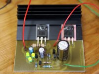
It is not quite clear to me (being a simple hobbyist) how James' PCB is to be used. I made a brand new one, straight forward from the schematic. If someone can use it I'll upload the drawing. It has star topology for both ground and output. I implemented bypassing the zeners and the LEDs with 0.1uF tantalum SMD caps. These have 20 ohm ESR at 100KHz. The regulator is up and running now, giving 24V out as I needed.
The zener is comprised of a 10V and a 13V in series and 4,4mA is passing. Both are 400mW units so the dissipated power for the 10V has to be 44mW and for the 13V 57mW. As always with zener diodes their output voltage is temperature dependent. When I blow over the PCB the circuit output voltage changes 0.1 to 0.2V. I guess it's good practice to make a solid case around the PCB to stabilize the temperature.
).The only explanation for the drain of Q1 being lower as the zener voltage is Q4 drawing too much current, as Q1 and Q4 are in series. When I measured a voltage drop over R4 all fell in place: Q3 was drawing base current.
It must be from the tube days Philips numbers the transistor pins from below. The BC550C was reversed. It survived though.
It is not quite clear to me (being a simple hobbyist) how James' PCB is to be used. I made a brand new one, straight forward from the schematic. If someone can use it I'll upload the drawing. It has star topology for both ground and output. I implemented bypassing the zeners and the LEDs with 0.1uF tantalum SMD caps. These have 20 ohm ESR at 100KHz. The regulator is up and running now, giving 24V out as I needed.
The zener is comprised of a 10V and a 13V in series and 4,4mA is passing. Both are 400mW units so the dissipated power for the 10V has to be 44mW and for the 13V 57mW. As always with zener diodes their output voltage is temperature dependent. When I blow over the PCB the circuit output voltage changes 0.1 to 0.2V. I guess it's good practice to make a solid case around the PCB to stabilize the temperature.
Attachments
- Status
- This old topic is closed. If you want to reopen this topic, contact a moderator using the "Report Post" button.
- Home
- Amplifiers
- Power Supplies
- The simplistic Salas low voltage shunt regulator