Yes, that's what I got too. 33 milliohms almost all across. If you're happy with that then I'm happy too that you're happy. It could very well be that I'm chasing wild geese here. BTW, we got lots of geese here. I love how they gaa-gaa around the city. Many people don't like them because the s**t all over the place. As far as I'm concerned, I say long live the geese! 
First things first. As far as I'm concerned, if you have questions, I see no reason why you should not ask them. salas said earlier something that a lot of people forget: these forums are here for some time, and people come after years something was posted, and learn something from your question or the answer to your question.
Now, about your question regarding the class A amp that draws 500mA at idle. You are assuming that this is a constant 500mA. The word "constant" is the key here. In real life it will not be as constant as you think. If it varies somewhere around the 500mA mark, and the psu output impedance is on the high side, the input voltage to your amp will vary too. By how much, that depends. Do you care about it? I don't know, that's something everyone has to decide for himself. Have you noticed something about salas? He seems to accept a circuit if it makes an audible difference. A lot of people will scorn this as subjective. I disagree with those people, because I think it's salas' right to decide for himself what sounds good. And it's your right to disagree. So, if you intend the regulator/psu to be part of some device that you ultimately will listen to, the ultimate test is to actually build it, listen to it, and then decide if it's worth it. Sorry to be long winded about this.
About measuring these circuits, I would certainly be curious about real life measurements. If anything, I encourage you to build v1. Many people are using that and are happy with it, after they compared it to alternatives. As far as v2 is concerned, that's very experimental still, and I'm still working on it. However, if anyone wants to go ahead and build it, who am I to disagree?")
Now, about your question regarding the class A amp that draws 500mA at idle. You are assuming that this is a constant 500mA. The word "constant" is the key here. In real life it will not be as constant as you think. If it varies somewhere around the 500mA mark, and the psu output impedance is on the high side, the input voltage to your amp will vary too. By how much, that depends. Do you care about it? I don't know, that's something everyone has to decide for himself. Have you noticed something about salas? He seems to accept a circuit if it makes an audible difference. A lot of people will scorn this as subjective. I disagree with those people, because I think it's salas' right to decide for himself what sounds good. And it's your right to disagree. So, if you intend the regulator/psu to be part of some device that you ultimately will listen to, the ultimate test is to actually build it, listen to it, and then decide if it's worth it. Sorry to be long winded about this.
About measuring these circuits, I would certainly be curious about real life measurements. If anything, I encourage you to build v1. Many people are using that and are happy with it, after they compared it to alternatives. As far as v2 is concerned, that's very experimental still, and I'm still working on it. However, if anyone wants to go ahead and build it, who am I to disagree?
I was checking out another regulator which is being worked on currently. It is an interesting shunt regulator too, and I was trying to help with its development a bit earlier. Today I managed to run it next to v2 and this is the output impedance plot.
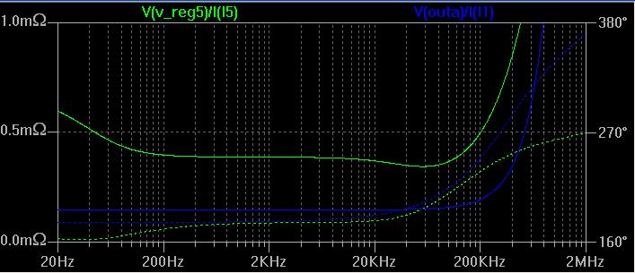
We should not read too much into such plots, but v2 does look promising.
We should not read too much into such plots, but v2 does look promising.
A tiny bit worse with the irf9540. Here's something that surprised me with v2. The 9240s seem to work quite a bit better in this circuit than other mosfets. Even more of a surprise: using a darlington to drive the mosfets (both) gives a significant boost in performance. In particular I tried mpsa77. And this is while all other features stayed about the same (meaning it didn't start oscillating).
Edit: 9510 a lot worse (20-30db worse); 9610 also worse, but a bit better than 9510. Does it surprise you? Because it does me. In v1 9610 actually seems better (if I remember correctly) than 9240.
Edit: 9510 a lot worse (20-30db worse); 9610 also worse, but a bit better than 9510. Does it surprise you? Because it does me. In v1 9610 actually seems better (if I remember correctly) than 9240.
No it does not surprise me. I just know that people will say try ''faster'' Mosfets for V2 at a point.
Just see the transcoductance curves of faster TO-220 Mosfets, see the numbers they hover around, and watch how they diminish with heat. There lies the key. 9240 is 5 to 6 times stronger and it has a much bigger die, and body to sink.
9240 I did not pick just so. Its an all rounder, truly robust, cools off better, fastens easier. It will not oscillate, and gives better bass. Plus it scales up a lot. Its 12A. I use 3 times less than max for no problems with constant current. It can work up to 4A constantly, breaking no sweat with proper sinks. It already works for many months in V1 shunt @ 3A on a 2X10W T-Amp making it sound like a 300B SET but with better bass and analysis, and no DHT hum of course. Total background and buzz silence.
' morning all, or evening to most!
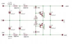
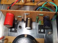
Sorry about the faint outlines for the components and the invisible donuts - I'll fix this today and also correct those transistors Q2, Q3.
The power fets (IRFPs) seem to be okay (g, d, s - left to right with metal back down, legs towards you, yes?) - I think the offset pad for the Gate is misleading and when the drawing is corrected, it'll be much clearer - the pcb is intended to mount parallel to a vertically heatsink (case, chassis, etc) and has 2 x 10mm standoffs at the bottom - the IRFPs have long 14mm leads that just bend UP to directly solder onto the copper.
You can also mount them on the same side as the other components, but need to bend the IRFPs away from the pcb edge to give better access to the output + terminal - it's quite suitable for the "Neutrik" pins (stripped down power connector pins) but IS a bit limiting and I'll do something about it, too (bit slow these days!)
Okay. The size of the board is 70mm x 30mm - a lot bigger than Peter D. would make it, but this is just a "starter" layout.
The IRFPs are 40mm apart.
... and the components that'll be most often changed need extra room and perhaps also extra donuts for when the first ones suffer soldered lift off!
The socket and plug are for ease of changing the zeners, particularly useful for those of us that require precise voltages. It's that Weidmuller device (same as the Phoenix ones) that has the screw terminals (so the larger size) - it can overhang the R3 and I'll squeeze ithis up later.
The caps are sized to 10mm with 5mm leads - not sure if this is enough, as I tend to go BIG! I remember Jan Didden emphasizing the fact that a very "bog standard" output electro is most useful here but I still sized them to suit the Elna Silmics and this should cater to most types. I have a Siemens Sikorel (axial cap standing on it's end) on the output and I do prefer the sound, and stability hasn't ever been a problem with this reg,
Onto the V2 design and the tl431 - over on the "Ultimate NOS 1541A dac" thread, John B. put together a few working circuits using the tl431 - it's about post #2559, on the 18 Feb this year - worth a look.
Curiously, Martin (Rupp) over on the "bipolar discrete shunt ..." has added a couple of small caps and it apparently has solved much of the stability problems. He's been amazingly, and "I take my hat off to him" - great stuff. I hope it sounds okay when it's finally tried out.
Okay, I'd better get to work and sort out these things.
Iko, thanks for the BC transistor error. Don't hesitate to be "really critical" (really) about any errors/faults and especially design flaws.
Also,not entirely happy with the first power reistor R1, either, and I'll thicken up the ground track (to 4mm wide) for C3 to the 0v o/p terminal.
Don't forget, folks. this is Salas' cct design - I'm just the dummy here playing "pcb Sudoko"!
jameshillj said:' morning all, or evening to most!
Sorry about the faint outlines for the components and the invisible donuts - I'll fix this today and also correct those transistors Q2, Q3.
The power fets (IRFPs) seem to be okay (g, d, s - left to right with metal back down, legs towards you, yes?) - I think the offset pad for the Gate is misleading and when the drawing is corrected, it'll be much clearer - the pcb is intended to mount parallel to a vertically heatsink (case, chassis, etc) and has 2 x 10mm standoffs at the bottom - the IRFPs have long 14mm leads that just bend UP to directly solder onto the copper.
You can also mount them on the same side as the other components, but need to bend the IRFPs away from the pcb edge to give better access to the output + terminal - it's quite suitable for the "Neutrik" pins (stripped down power connector pins) but IS a bit limiting and I'll do something about it, too (bit slow these days!)
Okay. The size of the board is 70mm x 30mm - a lot bigger than Peter D. would make it, but this is just a "starter" layout.
The IRFPs are 40mm apart.
... and the components that'll be most often changed need extra room and perhaps also extra donuts for when the first ones suffer soldered lift off!
The socket and plug are for ease of changing the zeners, particularly useful for those of us that require precise voltages. It's that Weidmuller device (same as the Phoenix ones) that has the screw terminals (so the larger size) - it can overhang the R3 and I'll squeeze ithis up later.
The caps are sized to 10mm with 5mm leads - not sure if this is enough, as I tend to go BIG! I remember Jan Didden emphasizing the fact that a very "bog standard" output electro is most useful here but I still sized them to suit the Elna Silmics and this should cater to most types. I have a Siemens Sikorel (axial cap standing on it's end) on the output and I do prefer the sound, and stability hasn't ever been a problem with this reg,
James, as you look at the board from above, G D S in that order. The last pin, S, should be connected to R2; you have D connected to R2. The other mosfet should also have the connections to pins 2 and 3 reversed.
Onto the V2 design and the tl431 - over on the "Ultimate NOS 1541A dac" thread, John B. put together a few working circuits using the tl431 - it's about post #2559, on the 18 Feb this year - worth a look.
James, I don't follow the connecton between the tl431 and v2 of this regulator. I might be missing something.
Curiously, Martin (Rupp) over on the "bipolar discrete shunt ..." has added a couple of small caps and it apparently has solved much of the stability problems. He's been amazingly, and "I take my hat off to him" - great stuff. I hope it sounds okay when it's finally tried out.
Yes, I have been active in that thread, as that design also interests me. I checked Martin's latest version and indeed it no longer oscillate. I didn't try very hard, lack of time, but seems ok. You might like the output impedance plot above comparing v2 with that.
[/b]
Okay, I'd better get to work and sort out these things.
Iko, thanks for the BC transistor error. Don't hesitate to be "really critical" (really) about any errors/faults and especially design flaws.
Also,not entirely happy with the first power reistor R1, either, and I'll thicken up the ground track (to 4mm wide) for C3 to the 0v o/p terminal.
Don't forget, folks. this is Salas' cct design - I'm just the dummy here playing "pcb Sudoko"! [/B]
I think it was somebody else that pointed out the bc error. It's ok, these are easy to fix. I think your effort to get the pcb in place is important. We all help how we can.
jam said:Ikoflexer,
How about something simpler like the one below with and wthout a current source...........another one from the mind of Chokey.
Jam
Jam, sorry, I can't possibly simulate all of these circuits, but how about this. I'll help you get started with ltspice which is free to download, and I'll give you the file and models needed to simulate salas v1 shunt, so you can get any of choky's regulators compared. I might do it a bit later. The complex choky design that you showed earlier seems really complicated, and unless it promises to be amazing, I would not put too much effort in it right now.
There are many good designs, one cannot test them all. IMHO we should concentrate now on making the one we have on hand as best we can. Then other people will start comparing, when they realize its good value and performance.
Ahhhh!!! The IRFP 9 240 penny finally dropped! And it's not even Friday!
This will require some contemplation - as you can see, I'm also rather good in the stupid department!
I'll see what "this ol'magic box" can do to fix it - I'll get back with some corrections. (And I was so pleased with how it all just came together - ah well, not any more, eh!)
Thanks for that.
This will require some contemplation - as you can see, I'm also rather good in the stupid department!
I'll see what "this ol'magic box" can do to fix it - I'll get back with some corrections. (And I was so pleased with how it all just came together - ah well, not any more, eh!)
Thanks for that.
jameshillj said:Ahhhh!!! The IRFP 9 240 penny finally dropped! And it's not even Friday!
This will require some contemplation - as you can see, I'm also rather good in the stupid department!
I'll see what "this ol'magic box" can do to fix it - I'll get back with some corrections. (And I was so pleased with how it all just came together - ah well, not any more, eh!)
Thanks for that.
Perhaps this will make you feel better. My first pcb for the original salas regulator, in a different thread, had two pins reversed on the mosfets.
It's easy to happen.jameshillj said:Ahhhh!!! The IRFP 9 240 penny finally dropped! And it's not even Friday!
No worries mate.
Just flip it at your leisure.Attachments
pcb adjustment
It seems that turning the Pfets around offers the most promising compromise, although I'm less confortable with the different layout direction. Just added the two BCs for confirmation.
Comments.
Let's see when I try to attach the thing in the browse thing below - you have to be patient with older folks!
Attachments
- Status
- This old topic is closed. If you want to reopen this topic, contact a moderator using the "Report Post" button.
- Home
- Amplifiers
- Power Supplies
- The simplistic Salas low voltage shunt regulator