That looks good to me. Here's a very good program that will make it easier to grab an image an save it as jpg, so that people don't have to unzip something to have a look at it.
http://www.mirekw.com/winfreeware/files/MWSnap300.exe
http://www.mirekw.com/winfreeware/files/MWSnap300.exe
Is Slew rate important for a power supply?
How do you simulate it?
I was just thinking, we are now at a very low output impedance is their any benefit in trying to lower it further (unless it also brings other improvements), as one contact can easily be 3mOhms (Neutrik Power Connector), a soldered joint is also in the milliohms http://findarticles.com/p/articles/mi_qa3776/is_200511/ai_n15845704/pg_2/?tag=content;col1 ?
Here is something else on the topic I found some time ago. The ideas seem good:
http://www.wenzel.com/documents/finesse.html
The bottom schematic mainly. If one wasn't requiring high currents then I suppose a 1ohm series resistor would do fine? Then lower the amplifier gain to just 15? Using 0.05ohm is sure to make construction difficult! Also, I am assuming this can be readily adapted for noise reduction in negative supplies.
I also saw a comment in the thread Salas linked saying that two LM317 in series, one as current reg followed by voltage reg, was an improved topology? Any thoughts on this? I suppose doing that then using the regulator noise shunt might be excessive
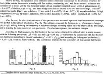
thanh, I would hope for sub 1 mOhm solder resistance, but maybe I'm just dreaming. The attached excerpt talks about 0.2 mOhm on average.
Dr.EM, I am familiar with that circuit and I have checked it out already (simulated, analyzed). Also tried various lm317 solutions. Still the regulator I'm right now is salas v1. Try it to see for yourself, then compare with a lm317 (series or however) and let us know what you find out.
Dr.EM, I am familiar with that circuit and I have checked it out already (simulated, analyzed). Also tried various lm317 solutions. Still the regulator I'm right now is salas v1. Try it to see for yourself, then compare with a lm317 (series or however) and let us know what you find out.
Attachments
Dr.EM said:
I also saw a comment in the thread Salas linked saying that two LM317 in series, one as current reg followed by voltage reg, was an improved topology? Any thoughts on this? I suppose doing that then using the regulator noise shunt might be excessive
In the world of 3 pin IC regulators this arrangement may be top of the tree. The salas design is essentially the same arrangement - a current source followed by a voltage regulator.
With the Salas design the regulation is achieved using shunt regulation rather that a series regulator.
Shunt regulators have the reputation of sounding best.
Preceding a shunt regulator with a current source ( as compared to simple resistor ) has the reputation of sounding excellent.
a well designed discrete component circuit will nearly always sound better than a chip - this is also my own experience.
If you add up all of these factors it means that a regulator similar to this nice one that Salas has presented here is likely to sound very good indeed and much better that the arrangement you describe above - that is why we are all here checking out this design - so I suspect you may find it hard to find much support on this thread for 3 pin regulators.
You may want to check out these pages:
http://www.tnt-audio.com/clinica/re...s_noise1_e.html
These four pages discuss noise in regulator circuits - which for me and I think many others regard as the major factor regulator design that leads to nice sounding audio. The final circuit presented just before he discusses batteries is a few steps away from Salas's circuit ( the main difference is that is does not include a current source )
hope that helps
mike
the link again
http://www.tnt-audio.com/clinica/re...s_noise1_e.html
this link does not work for me so perhaps try this link to a link
http://www.diyaudio.com/forums/showthread.php?postid=1825981#post1825981
")
http://www.tnt-audio.com/clinica/re...s_noise1_e.html
this link does not work for me so perhaps try this link to a link
http://www.diyaudio.com/forums/showthread.php?postid=1825981#post1825981
Sorry for all the questions.
1. What is the prefered range of Idss for the constant current sources (2sk170)?
2. With the impedance plots, is phase angle significant?
3. Will the phase angle indicate responsiveness or lag?
4. What about slew rate, is this worth measuring or is bandwidth good enough?
Just to let you guys know, I previously did measurements in the lab using 2sk170 as constant current sources and found that the Vishay J500 series current regulating diodes much more stable with changing voltage however they only go up to 4.7mA. They are absolutely rock steady.
Attachments
thanh1973 said:Is it ok to use 2sa970 and 2sc2240 instead of BC560, and BC550?
That is what I have handy.
In simulation the 2sc2240 gives a boost to output impedance in the low freq range. Seems to work. You'd probably be the first one to build it with these components.
I had to buy mine from ebay.
However I believe linear systems now make them.
http://www.linearsystems.com/datasheets/J500.pdf
http://www.linearsystems.com/index.html
However I believe linear systems now make them.
http://www.linearsystems.com/datasheets/J500.pdf
http://www.linearsystems.com/index.html
thanh1973 said:Sorry for all the questions.
1. Under Zener 5-7mA IDSS 170BL or GR 4-5mA, for low pinch off (critical). Has to work under Vbe. If that VL figure is pinch off on the Vishay PDF, they are ruled out for that position. 5-7mA is just enough to lock the Vref adequately. For BC550 CCS load 8.5mA (mean average of late 2SK170BLs from Spencer). Gives strong Gm to the BJT.
2. They will change a lot in reality. Cout and layout and cabling will intrude.
3. Don't know.
4. BW is enough.
*Can use better Isources or Vrefs if adequate. The V1 tried to take advantage of 170BLs that would be left out from the matching procedure of its partnering phono stage. Of course they ain't a bad choice at all. Under Zener one has to be a 170BL though, or something so low in pinch off. Toshiba again I guess.
Just want to add a quick comment regarding slew rate. I'm not sure we can translate directly the slew rate from the opamp world here. However, loosely speaking a high slew rate would point to good performance at high frequency. This is something that I've been trying to improve for some time, and only with the latest version of v2 I had some success. Whether that will make any difference in real life is yet to be seen. Suffice to say that all other things being equal a wider bandwidth is attractive to many people.
ikoflexer said:Suffice to say that all other things being equal a wider bandwidth is attractive to many people.
Depends on the sensitivity of audio circuit served and what comes from the wall and rectification. It may pass trash.
RC and CLC have been tried. Transformers up to 100VA have been tried. Quality of main filter capacitor was the most audible. RC to CLC not that strong, but audibly softer.
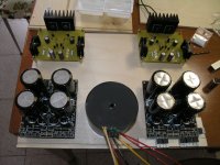
Nicoch and RCruz are playing a lot with parts and pre filters. They may help. Nicoch effort so far
Nicoch and RCruz are playing a lot with parts and pre filters. They may help. Nicoch effort so far
Attachments
Salas said:Depends on the sensitivity of audio circuit served and what comes from the wall and rectification. It may pass trash.
Have to disagree there.
Higher frequency response according to my understanding adds better high frequency PSRR in any circuit with feedback.
But we have to take care with stability other we start adding noise back in with spurious ringing caused by the instabilities.
- Status
- This old topic is closed. If you want to reopen this topic, contact a moderator using the "Report Post" button.
- Home
- Amplifiers
- Power Supplies
- The simplistic Salas low voltage shunt regulator