Thanks Ikoflexer
Could you tell me what the commands and the load are to replicate your tests? (I am very new to this.)
That will save me asking you to do them all the time.
I probably could have worked out how to do these but I have noticed that LTSPICE is very sensitive to the commands you give it in terms of what you get out.
So I wanted to compare exactly with what you had done previously.
Anyway thanks again.
Unfortunately I don't have the time to do a better job, but I hope you find this useful:
http://www.cs.toronto.edu/~relu/audio/ltspice/tutorial-spice-zout.html
If you have any questions, fire away.
http://www.cs.toronto.edu/~relu/audio/ltspice/tutorial-spice-zout.html
If you have any questions, fire away.
Thanks for the link. That helps immensley.
I have some questions.
If a circuit is biased high enough into class A, that it never draws more than the quiescent curent, and hence the current at the output of the power supply is constant (ie unchanging) is bandwidth still relevant?
My feeling (I have no experience on this) then is that output impedance at 0Hz (pure DC) is more important than at high frequency (or any frequency for that matter).
If my thinking is completely wrong please help me understand (remember my question refers to highly biased class A circuits).
thanh1973 said:Thanks for the link. That helps immensley.
I have some questions.
If a circuit is biased high enough into class A, that it never draws more than the quiescent curent, and hence the current at the output of the power supply is constant (ie unchanging) is bandwidth still relevant?
My feeling (I have no experience on this) then is that output impedance at 0Hz (pure DC) is more important than at high frequency (or any frequency for that matter).
If my thinking is completely wrong please help me understand (remember my question refers to highly biased class A circuits).
If such a thing existed in the real world, as a pure constant current draw, then we wouldn't worry so much about the output impedance of the power supply circuit.
Re: Simple but expensive
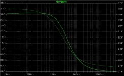
I'm not sure what you mean by it working. It would certainly provide some voltage at the output. However, we've established that it has very poor output impedance. If we assume a somewhat constant load, perhaps output impedance (load regulation) is not something you think you need, so we'll ignore that. How about the AC component in the input voltage though? That would be the line regulation. Post #100 on the previous page shows a pretty poor line regulation for this circuit. A simple lm317 may give much better performance for very little money. I still don't know if I understood your question correctly.
thanh1973 said:Would this work?
See Attachment (LTSPICE File)
I'm not sure what you mean by it working. It would certainly provide some voltage at the output. However, we've established that it has very poor output impedance. If we assume a somewhat constant load, perhaps output impedance (load regulation) is not something you think you need, so we'll ignore that. How about the AC component in the input voltage though? That would be the line regulation. Post #100 on the previous page shows a pretty poor line regulation for this circuit. A simple lm317 may give much better performance for very little money. I still don't know if I understood your question correctly.
James PCB progress
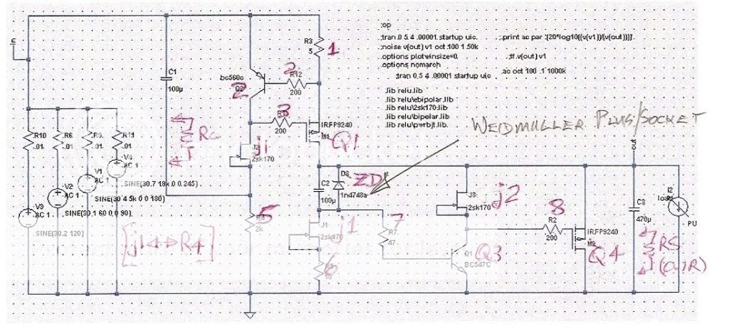
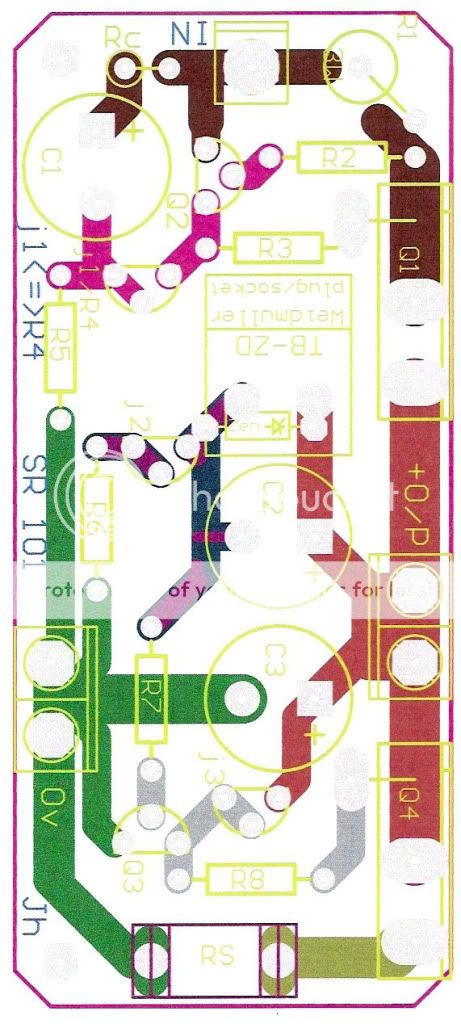
James has sent me a couple of files to upload. You can see components side and the particular schematic he based it on. The handwritten numbers are his changes on component numbers so to have a more logical order. Ignore everything left to C1, since that stuff is simulator's. He provides for a bootstrap cap damping resistor (RC), Jfet or resistor divider (J1/R4), a socket for Zener reference or whatever with the Vref arrangement you may fancy, plus an Rs option for local feedback to the shunt Mosfet, doubling as a means to check its current. His explaining comments will follow soon I guess.
I think that BC560C,550C are CBE and must be reversed, but this can be easily done until the final copper side file. Please review for other stuff or suggestions to James.
Thanks James!")
James has sent me a couple of files to upload. You can see components side and the particular schematic he based it on. The handwritten numbers are his changes on component numbers so to have a more logical order. Ignore everything left to C1, since that stuff is simulator's. He provides for a bootstrap cap damping resistor (RC), Jfet or resistor divider (J1/R4), a socket for Zener reference or whatever with the Vref arrangement you may fancy, plus an Rs option for local feedback to the shunt Mosfet, doubling as a means to check its current. His explaining comments will follow soon I guess.
I think that BC560C,550C are CBE and must be reversed, but this can be easily done until the final copper side file. Please review for other stuff or suggestions to James.
Thanks James!

thanh1973 said:
My feeling (I have no experience on this) then is that output impedance at 0Hz (pure DC) is more important than at high frequency (or any frequency for that matter).
If my thinking is completely wrong please help me understand (remember my question refers to highly biased class A circuits).
You're not completely off-base here, but the problem is that no such circuit exists in reality. You are absolutely correct that a circuit with more constant current draw can tolerate a less capable regulator. Conversely a circuit where the current consumption slews all over the place needs a great regulator.
In reality it's good to focus on both. Try to make circuits with constant current draw, or balanced circuits where the current flows in local loops, or try to make the quiescent current much greater than the dynamic current. Then determine the dynamic current and the output impedance you can tolerate and design a regulator having that output impedance.
You're wrong about zero Hz, however. It's desirable to have a flat output impedance in the passband, because otherwise you will skew your circuit's frequency response.
Good start guys!!! A few comments, some of which you can safely ignore.
* my first concern would be the pins on the irfp9240. In my datasheet it shows as G D S, 1 2 3
* the mosfet gate resistors, as close as possible to the gate, even if it looks ugly
* the signal path, in -> out, should be as straight as possible; this helps with higher frequency response
* C2 can be safely smaller
* should C3 be closer to the output?
This is it for now.
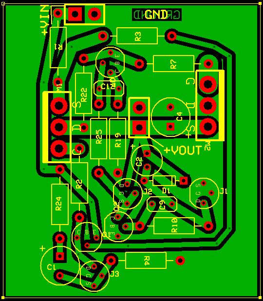
Edit: I can show this ugly duckling that I'm currently working on. I am not suggesting you should do it this way, but it seems appropriate to compare notes.
As always, comments appreciated greatly.
* my first concern would be the pins on the irfp9240. In my datasheet it shows as G D S, 1 2 3
* the mosfet gate resistors, as close as possible to the gate, even if it looks ugly
* the signal path, in -> out, should be as straight as possible; this helps with higher frequency response
* C2 can be safely smaller
* should C3 be closer to the output?
This is it for now.
Edit: I can show this ugly duckling that I'm currently working on. I am not suggesting you should do it this way, but it seems appropriate to compare notes.
As always, comments appreciated greatly.
ikoflexer said:
* my first concern would be the pins on the irfp9240. In my datasheet it shows as G D S, 1 2 3
* the mosfet gate resistors, as close as possible to the gate, even if it looks ugly
Yes, James must correct along with the BCs.
Salas said:How do you heatsink m1 without obstruction especially in heavier settings?
Yes, good catch! It would, and I'm still trying to push things around to come up with a better solution. This is very preliminary, just started on it, playing with ideas.
This is a pcb for the experimental V2, you probably noticed already. I've stumbled upon a small change which further improves performance. Very small steps, but at this level, I'm happy even with incremental improvements. We'll see if in real life it proves to be good.
To the contrary! The standard version will be out soon on excellent (and debugged) PCB from James. 10s of people are extremely happy with it by now in many voltage and current settings. That is a done and out shunt.
Running a possible V2 plan is healthy. We will recommend it additionally only when you will say that it actually sounds better to SR1 on a final PCB of yours without oscillations. That's all. Brazillian soccer. Fast, short passes to the goal.
Running a possible V2 plan is healthy. We will recommend it additionally only when you will say that it actually sounds better to SR1 on a final PCB of yours without oscillations. That's all. Brazillian soccer. Fast, short passes to the goal.
- Status
- This old topic is closed. If you want to reopen this topic, contact a moderator using the "Report Post" button.
- Home
- Amplifiers
- Power Supplies
- The simplistic Salas low voltage shunt regulator