A few questions about building some Reflektor type supplies:
1. Is the MTP3055VL as M2 a good choice for as high as 12V out? It looks it, but I wonder if it might be getting rather close to its 15V gate to source spec. I would think the voltage would slowly climb to around 11V, and then never vary by even as much as 200mV during operation, drift included, but my knowledge is minimal, here.
2. Is there any particular downside to using 2SK117BL, instead of 2SK117GR, for J1? I have quite a few 2SK117BLs, nothing else to use them for, but I don't quite understand what the selection process for that JFET entailed.
3. Would there be any possible improvement with Q1/Q2 and Q3/Q4, if they were/ bonded together? Like thermal paste, and zipties or heatshrink keeping pressure on them.
Last edited:
1. Its OK for 12V out. VGS will remain the same as in typical Ref-D
2. Just degenerate the BL enough with RR value good for circa 2mA bias
3. If matched for hFE also yes they can be bonded, that is why they are facing each other on the Ref-D board so a perfectionist can facilitate that, although this current mirror design is rather tolerant for mismatch
2. Just degenerate the BL enough with RR value good for circa 2mA bias
3. If matched for hFE also yes they can be bonded, that is why they are facing each other on the Ref-D board so a perfectionist can facilitate that, although this current mirror design is rather tolerant for mismatch
The new LT1028 arrived today. Popped it in and.... nothing changed  .
.
Seems like the first one pretty much survived all the abuse
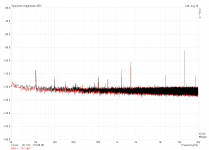
Here's what I did: after unsoldering the old opamp I fitted a socket for easy replacement. To protect the inputs I added two anti-parallel diodes each from pins 2 and 3 to ground. Replaced the two back-to-back electrolytics input cap with a 100uF/100V bipolar one. Shorted the input, put in the new opamp, shut the case, applied power, checked for 0V at the output with DMM, connected output to soundcard and did the measurement.
Red: Old opamp in socket
Black: New opamp in socket
So until now the new opamp didn't see any current or voltage at its inputs except for their own offsets and performance is the same as before. Any thoughts?
.Seems like the first one pretty much survived all the abuse
Here's what I did: after unsoldering the old opamp I fitted a socket for easy replacement. To protect the inputs I added two anti-parallel diodes each from pins 2 and 3 to ground. Replaced the two back-to-back electrolytics input cap with a 100uF/100V bipolar one. Shorted the input, put in the new opamp, shut the case, applied power, checked for 0V at the output with DMM, connected output to soundcard and did the measurement.
Red: Old opamp in socket
Black: New opamp in socket
So until now the new opamp didn't see any current or voltage at its inputs except for their own offsets and performance is the same as before. Any thoughts?
Attachments
protection diodes from supply rails to both inputs prevents the pair of inputs going much outside the supply rails.
Even better to create a pair of slightly lower (protection) supply rails so that the diodes give protection just inside the opamps supply rails. eg, mains supplies @ ±15Vdc
Protection rails at ±14Vdc
Diodes limit excursions to 14.6V, just less than the main rails.
Even better to create a pair of slightly lower (protection) supply rails so that the diodes give protection just inside the opamps supply rails. eg, mains supplies @ ±15Vdc
Protection rails at ±14Vdc
Diodes limit excursions to 14.6V, just less than the main rails.
Diodes to ground should limit excursion to ±0.6Vdc, which is plenty for noise testing. They also help shunting the big current spikes to ground that arise when you connect the DUT with 15Vdc to the input. But then again, it seems to me that the internal protection diodes managed that just as well, albeit the datasheet states that the input current shouldn't exceed 25mA.
OK, so Vgs gets set through R4-R6, and rests there. Sorry for being weak on theory, but I'm one of those computer and uC guys trying to learn more in the strange world of analog circuitry, and FETs are mysterious magic boxes, operated by sorcerers, from my current PoV1. Its OK for 12V out. VGS will remain the same as in typical Ref-D
. I get the current mirror and LEDs part, but then my comprehension of what's going on gets spotty.R4 is just a gate damper to prevent oscillation from stray inductance because the gate is capacitive. The bias from the shunted current will open M2 to some Vgs which will set the bias current through R6 and the mirror. R6=JFET Idss mod can fix that current with very high impedance too and boost the open loop gain adding some behavior of its own also.
Boards arrived from China, here's the first working Low Current Dual Salas. Matching of the LED bargraphs is not that great (only ordered two), output voltages are around 12.1V and 12.5V. Little lower than I thought actually. Didn't check anything else than output voltage and total current consumption w/out load yet, but things look fine so far. Those graphs look absolutely gorgeous when applying power, because first only three LEDs each will light up and after a short delay the remaining 7 come on with a little fade-in .
.Attachments
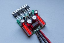
A looker indeed. Its their big noise filter capacitor coming up to ref voltage fade in effect. But it would take the addition of series small value rheostat trimmer(s) to ensure symmetry since we can't have exact total Vf by exchanging LED elements like people do in DCB1 etc. I got a couple of samples to use too when the opportunity comes and I saw they are near but never too near especially between two bars than for elements within a bar. There are situations where V+/V- total symmetry is not required though. Depends on the circuit the PSU is used for.Boards arrived from China, here's the first working Low Current Dual Salas. Matching of the LED bargraphs is not that great (only ordered two), output voltages are around 12.1V and 12.5V. Little lower than I thought actually. Didn't check anything else than output voltage and total current consumption w/out load yet, but things look fine so far. Those graphs look absolutely gorgeous when applying power, because first only three LEDs each will light up and after a short delay the remaining 7 come on with a little fade-in
Great, we will enjoy to watch. In what gain is your modified pearl set?
Its taken a while but eventually got it uploaded. Gain is around 56dB. Feels a little too high for this setup so i may reduce it.
https://www.youtube.com/watch?v=55jzwtCp04I
I'll be posting another video soon of the new power amp and whole Turn Table setup.
PS I bought the Denon cartridge; it does not disappoint
Cheers
Dom
Congratulations. A very involved but finely executed build. SSLV1.2R & Pearl II fully hand made, not an easy task. Very organized raw PSU too.The video photos sequence are nice. I think you could add explanatory captions as the images story unfolds. Let us know when you will upload next. Denon is making musical sense accessible with less fuss than many other makes in most systems, well done. 
Congratulations. A very involved but finely executed build. SSLV1.2R & Pearl II fully hand made, not an easy task. Very organized raw PSU too.The video photos sequence are nice. I think you could add explanatory captions as the images story unfolds. Let us know when you will upload next. Denon is making musical sense accessible with less fuss than many other makes in most systems, well done.
Thanks Salas
Just need to get the tracking weights setup on my JBE turntable then I will post the full setup .
Unfortunately they were missing (as well as the PSU) when I recieved the JBE turntable so im going to need to machine new weights etcetera.You think you probably need to trim 6dB out of the phono sensitivity since the DL-110 is strong enough? Keep in mind that for 10dB SPL less we humans tend to agree its half the volume in psychoacoustics. Thus weigh the how many dB to trim decision as to both have good low level dynamics and to not getting too loud early on the volume pot. If you got an SPL meter use it. System gain optimum depends a lot on how sensitive the speakers are and on how far you sit from them.
P.S. You could also add music on the videos along captions. Better an actual needle drop track that you can record on your PC.
If titled as "Denon DL-110 plays through my DIY phonostage" or "Vinyl record sound through my DIY gear" or something like that, it will gather loads of YouTube hits through the search machines. Thousands even.
If titled as "Denon DL-110 plays through my DIY phonostage" or "Vinyl record sound through my DIY gear" or something like that, it will gather loads of YouTube hits through the search machines. Thousands even.
Hi all,
I'm building a spice model of the Reflektor D to help me understand the way it works while I'm waiting for the board of the group buy to arrive.
It's almost there but I can't find a model for the MTP3055VL. Does somebody have its spice mdoel or maybe a suggestion for a part that can reasonably well replace it in the model?
Thanks
- Status
- This old topic is closed. If you want to reopen this topic, contact a moderator using the "Report Post" button.
- Home
- Amplifiers
- Power Supplies
- The simplistic Salas low voltage shunt regulator