I would check the working one's everything Vbe and Vgs against its analogous non working one to troubleshoot. Also add the zener + resistor starter. Maybe just a kickstart issue. Why C102 103 202 203 are 4.7uF instead of 47uF BTW? Just a schematic designation error?
I've been comparing the working one against the non working one. Don't have any voltage over the variable resistor. Need to double check the connections although the connections look pretty clean. Still unsure about the negative regs. I just tried searching for the zener and resistor starter in this thread but didn't find it specifically. Do you have a post number?
I'm building V1.2R the schematics on post 3200 http://www.diyaudio.com/forums/powe...-voltage-shunt-regulator-320.html#post2361983 and it has C102 103 202 203 as 4.7uF?
Check Q106 and Q109 on the positive shunt...... never built negative shunts and all my V12r worked from the start.
PS: The one that got away is now alive and kicking.... can confirm that using IRF9530 is a good option instead of the 9240 or 9140")
Thanks RCruz I'll check Q106 and Q109.
I've been comparing the working one against the non working one. Don't have any voltage over the variable resistor. Need to double check the connections although the connections look pretty clean. Still unsure about the negative regs. I just tried searching for the zener and resistor starter in this thread but didn't find it specifically. Do you have a post number?
I'm building V1.2R the schematics on post 3200 http://www.diyaudio.com/forums/powe...-voltage-shunt-regulator-320.html#post2361983 and it has C102 103 202 203 as 4.7uF?
There is a force lines spanning RC termination with 4.7uF and a 47uF electrolytic across that RC. Alright, so the vertical ones are 47uF in your layout, I did not notice well. Forget it.
Use a 9V Zener and 6.8k resistor in series from the force output line to the bottom of the main CCS setting resistor. Cathode towards the setting resistor in positive regs, cathode towards the force line in negative regs.
Is there a Vbe voltage from the BJT that nests the LSK which current is to be controlled by the VR? Change that BJT if dead. Else it should be the LSK.
Hi Salas, figured out what the problem was. The two negative regulators had their IRF540 drain and source internally shorted (not completely but around 300 ohm). I replaced them and all is fine. The positive regulator that wasn't working took me ages to figure out what was wrong: when i screwed down the sensing wires i must have put too much force on the terminal block as the track underneath had broken just a micrometer it would appear so creating an open circuit. A quick blob of solder and its working fine now.
Since (from reading this thread) I noticed you like a picture or two I will post pictures of the complete assembly shortly
Alright, good news. Congrats then! Do they kick start on their own without that additional helper Zener & resistor thing?
Yes they all start fine without the resistor & zener however I've noticed that one of the negative regulator LEDs is flashing . I will need to investigate further.

Notes on using Salas for Dam1021 R-2R DAC
Hi Salas
Here are something that we found when using BiB Salas for the Dam1021 DAC.
Yesterday, we tested the dac + BiB comb with an APx-515.
We identified several things which other DIYers (using BiB Shunt reg) need to pay attention to.
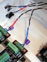
1. one may add cap at the output of BiB Shunt Reg (see pic below)
2. do not use remote sensing
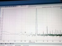
After these two modification, FFT analysis showed that there was a drop in noise floor of about 20dB. Yes! 20dB! Simply by looking at the FFT graph, we founded that there was also slight improvement in harmonic distortion too.
We know that other guys here may have experience in using Salas for other digital stuffs, esp. DAC. Please feel free to share your observation and reminders.
Hi Salas
Here are something that we found when using BiB Salas for the Dam1021 DAC.
Yesterday, we tested the dac + BiB comb with an APx-515.
We identified several things which other DIYers (using BiB Shunt reg) need to pay attention to.
1. one may add cap at the output of BiB Shunt Reg (see pic below)
2. do not use remote sensing
After these two modification, FFT analysis showed that there was a drop in noise floor of about 20dB. Yes! 20dB! Simply by looking at the FFT graph, we founded that there was also slight improvement in harmonic distortion too.
We know that other guys here may have experience in using Salas for other digital stuffs, esp. DAC. Please feel free to share your observation and reminders.
Attachments
Hi Salas
Here are something that we found when using BiB Salas for the Dam1021 DAC.
Yesterday, we tested the dac + BiB comb with an APx-515.
We identified several things which other DIYers (using BiB Shunt reg) need to pay attention to.
1. one may add cap at the output of BiB Shunt Reg (see pic below)
2. do not use remote sensing
After these two modification, FFT analysis showed that there was a drop in noise floor of about 20dB. Yes! 20dB! Simply by looking at the FFT graph, we founded that there was also slight improvement in harmonic distortion too.
We know that other guys here may have experience in using Salas for other digital stuffs, esp. DAC. Please feel free to share your observation and reminders.
Hi thanks for sharing,
I think Dimdim has also reported something on this in his blog.
I am going to try with reflektor D, will see how it performs in this context.
Hi Salas
Here are something that we found when using BiB Salas for the Dam1021 DAC.
Yesterday, we tested the dac + BiB comb with an APx-515.
We identified several things which other DIYers (using BiB Shunt reg) need to pay attention to.
1. one may add cap at the output of BiB Shunt Reg (see pic below)
2. do not use remote sensing
After these two modification, FFT analysis showed that there was a drop in noise floor of about 20dB. Yes! 20dB! Simply by looking at the FFT graph, we founded that there was also slight improvement in harmonic distortion too.
We know that other guys here may have experience in using Salas for other digital stuffs, esp. DAC. Please feel free to share your observation and reminders.
Digital applications may have laborious multilayer implementation where the proper nodes to sense are not the ones labeled as power in. Not even accessible some times. In such a case, closing the sense circuit locally at the reg may present better results indeed. Their fed back noise behavior can be a complex matter too. Especially when high frequency. Best practice is what you did, i.e. measure and decide best way to connect on a specific application. Glad that you achieved a significantly better overall FFT in the end.

P.S. There is also board position for output electrolytic instead of R-C film capacitor termination. C103 (for R107 use jumper).
Salas, I will take note of it.
In the BiB building guide pdf,
you mention something like "for sensitive digital or MC phono.... use electrolyte cap".
As the BiB shunt reg is used in a DAC, most of the noise is high frequency,
I will experiment with adding 0.1u ceramic and inductor. If I manage to clear some more 3~6dB of noise or lower 2~3dB of harmonics, I will be very happy.
The guide refers to the vref filter capacitor option also. There is alternative position under your other ERO cap, the one towards the center. Use up to 1000uF there for best noise, especially 1/f. Polymer fits too. Clocks appreciate. Additions to the rail can skew phase and lead to instability. But you got access to $7000 AP analyzer and you will see what works best in the specific application. It will be nice to share exact config with the rest of guys for that DAC and shunt, because not everybody has digital signal analyzer access. If those best practices will be also subjectively felt to all, they will certainly appreciate and let you know.Salas, I will take note of it.
In the BiB building guide pdf,
you mention something like "for sensitive digital or MC phono.... use electrolyte cap".
As the BiB shunt reg is used in a DAC, most of the noise is high frequency,
I will experiment with adding 0.1u ceramic and inductor. If I manage to clear some more 3~6dB of noise or lower 2~3dB of harmonics, I will be very happy.


Very nice builds. Both orderly and aesthetically advanced internals. For what kind of phono stage design you use it for? Do I see TO-92s in parallel for low mc? Nice mission 774 arm. I use a modified one myself.
Thanks Salas. Its a modified Pearl 2 I'm using for the pre amp. Yes four Toshiba 2SK170 in parallel for the input first stage. I have a cheap Audio Technica cartridge on the 774 at the moment and plan to upgrade it. Any suggestions on which cartridge?
Tell me your budget and I will suggest.
I wouldn't like to spend anymore than £250.

Denon DL-110. Legendary cart. Pearl is not that sensitive for under 1mV cartridges. That one is 1.6mV high MC and within budget. I also suggest you put 47uF/63V good quality electrolytic underneath the C1 4.7uF PP capacitor in each V1.2R when it is feeding a phono. Directly to C1 pins, (-) towards Q9. Reverse for negative version.
http://www.amazon.co.uk/Denon-DL110-Moving-Coil-Cartridge/dp/B000Q33ONG
http://www.amazon.co.uk/Denon-DL110-Moving-Coil-Cartridge/dp/B000Q33ONG
Denon DL-110. Legendary cart. Pearl is not that sensitive for under 1mV cartridges. That one is 1.6mV high MC and within budget. I also suggest you put 47uF/63V good quality electrolytic underneath the C1 4.7uF PP capacitor in each V1.2R when it is feeding a phono. Directly to C1 pins, (-) towards Q9. Reverse for negative version.
Denon DL110 Moving Coil Cartridge: Amazon.co.uk: Electronics
Thanks Salas, I might just order that Denon as I have read loads of good reviews. I'll also try the 47uF // 4.7uF. I'm planning to create a little build log video of the project and will post a link to it. (Almost finished the editing)
Hi,
I want to build Salas Reflektor to use in my amplifier buffer. It is the first time I try with a Shunt Regulator so I have some questions that need your help:
- The circuit need about 50mA / channel so 100mA in total. Is it ok if I set CCS current about 300mA? I think it is the minmum recommend current value?
- Is it ok to use FQP3N30 FQP3N30combo for M1 & M2 (two mosfets). Any change I need apply if I use those two?
- Did anyone compare SQ of Reflektor to Salas 1.2R or 1.1? Will I lost something if I go with the easier Reflektor?
- Status
- This old topic is closed. If you want to reopen this topic, contact a moderator using the "Report Post" button.
- Home
- Amplifiers
- Power Supplies
- The simplistic Salas low voltage shunt regulator