It's a mistake by itself, since it reduces bandwidth (and degrades precision) unneccessarily, but if considered as a goal, why not implemented with 10 times higher resistors? Small value resistors usually have a not negligible inductance (plus track inductance). 20 nH and 0.5 ohm forms a 4 MHz low pass filter. OK, I know BW is already limited to 50 kHz, but could have been much better if gain of first stage would be much lower, second stage would be higher, and IC8 were in the place of IC7A (where it was stable).
60 dB gain in 1 stage is never the optimal choice.
I didn't try other configurations, but in other threads I read about LNAs the common choice seems to be this one, because noise performance only gets worse the more stages you use. Of course I'd like to see a better design from you
") .
.Why C45 is in the common mode feedback path?
The whole purpose of IC8 is to function as a buffer, together with adjacent parts like C45, to bootstrap R11 and R12 to better the common mode rejection. Adapted this from Whitlock, it's part of his InGenius patent. It's not supposed to be a 1028, but something cheap like an OP07.
What is the purpose of this and why in this topic?
Like it has been said, to better measure the performance of the regulator this thread is about. Input impedance will thus be pretty low, so what's wrong about going low-value for feedback resistors? The discrete buffers might also help to take some load off the opamps so that they don't warm up as much and thus stay less noisy. If this all sounds unreasonable, I'd be probably better off buying an integrated INA, but where's the fun in that?
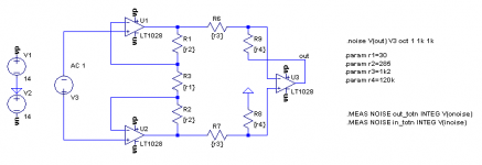
Just did a quick noise sim with the simplified circuit attached. Used the basic resistor values from the AD8428 datasheet and modified the ratios for different gain configurations. Adjusted them so that the gain was very close to 2000 each time.
Code:
R1	R2	R3	R4	noise density
---------------------------------------------
30.001	30k	12k	12k	1.39637nV
30.15	3k	12k	120k	1.40547nV
30	285	1k2	120k	1.42901nV
0.4804	240	470	940	1.20741nV
Attachments
with a gain of 2000times and noise bandwidth of 100kHz the output noise of the amplifier will be:
output noise = 1.2nV * sqrt(100kHz) * 2000gain = ~ 0.76mVac.
The first chip would need a gain bandwidth product of >1000(first stage gain) * 100kHz > 100MHz
If you reduce your target from +60dB gain to +40dB gain you start to get a usefully low noise at the output and reduce the GBWP requirement to greater than 10MHz.
If you could reduce the input referred noise to below 1nV/rootHz, then you will have a useable +40dB LNA.
Last edited:
with a gain of 2000times and noise bandwidth of 100kHz the output noise of the amplifier will be:
output noise = 1.2nV * sqrt(100kHz) * 2000gain = ~ 0.76mVac.
The first chip would need a gain bandwidth product of >1000(first stage gain) * 100kHz > 100MHz
Nothing wrong with 20kHz bandwidth IMHO. Output noise will benefit.
If you reduce your target from +60dB gain to +40dB gain you start to get a usefully low noise at the output and reduce the GBWP requirement to greater than 10MHz.
I'd be fine with 40dB. What do you consider usefully low noise at the output? Your calculation above for a gain of 2000 should be about as good as it can get for this much gain and a "single" input stage.
If you could reduce the input referred noise to below 1nV/rootHz, then you will have a useable +40dB LNA.
This could be achieved by paralleling multiple of those INAs, which in turn would make the whole thing more expensive and put it close to the point of diminishing returns. After all I'm not heading to make the ultimate and best performing LNA out there. I only try to achieve the optimum performance with some off-the-shelf parts that I can get hold of for a reasonable amount of money. The parts for the discrete buffers exist in the parts bin and two LT1028 are still cheaper than a single, similar-spec'ed INA.
I would not want an LNA that gave a significant noise reading when there is zero ohms connected to the input of the LNA.
That would apply whether I was using an Vrms on a DMM or using the most sensitive setting on my scope.
My first scope had a switchable +20dB preamp to give a more sensitive lowest scale. It was noisy and it reduced bandwidth by factor of 10. I rarely used it.
I would want an LNA to perform better than that switchable pre-amp.
Try using +40dB (100x) first and see how well it performs. Then try the +60dB (1000x). Finally try the +66dB (2000x)
If you achieve those predicted input referred noise levels, then I would expect a 20kHz and 100kHz band limit @ +40dB to perform very well.
Last edited:
That sounds reasonable. Unfortunately I see a big problem with parallel discrete INAs. Even if I use only two of them (for 5 opamps in total) I'd have to match 14 resistors to better than 0.1%. The sim shows a worst case CMRR of barely 60dB for 0.1% resistors, which is pretty bad for just popping in some resistors without any matching. I'd have to make sure that trimming with a file is a useful alternative to buying bunches of precision resistors, since CMRR is what I'm after.
You miss the point I made.
Your +66dB proposal with the 1.2nV/rtHz to 1.4nV/rtHz give a lot of noise.
I estimated from your predictions that the output noise would be around 0.76mVac
But if you lower your target to +40dB with your present noise prediction you get a more acceptable output noise.
The estimate is:
Vnoise at output = 1.4nV * sqrt(100k) * 100 = 0.044mVac. It effectively reads zero on a 199.9mVac DMM for a 100kHz bandwidth and you get to use a manageable >10MHz opamp to get there. A scope on a 2mV/div will also read near a flat line with that noise output for a zero input signal. Vpp is ~6* Vac accounting for the random peaks above the average. i.e. 0.044mVac gives an average Vpp of 0.13mVpp and a maximum of 0.25mVpp You get a chance to see small signal effects above that near flat line.
Once you have that running. You can see how far you can push your existing proposal with extra gain, or how low you can push the input referred noise by using some form of ultra low noise input.
There are Members here that talk about circuits with input referred noise <<0.5nV/rtHz
If CMRR is important for you, I have a bad news: increasing gain decreases CMRR. You dont see it, because simulation assumes totally identical OPAs, but as soon as they become different (like in real life), gain of them starts to deviate. The less the feedback, the more they will differ. So maybe you can decrease noise by a fraction of a dB by setting too much gain, but also decrease CMRR by many dBs at higher freq.
But I also have a good news: as long as resistors determine symmetry, you have to adjust only 1 of them! You can easily paralel as many INA as you want. I repeat: only as long as resistors determine gain. But in order to assure this, you need strong feedback, 40 dB at least, inside measurement bandwidth.
But I also have a good news: as long as resistors determine symmetry, you have to adjust only 1 of them! You can easily paralel as many INA as you want. I repeat: only as long as resistors determine gain. But in order to assure this, you need strong feedback, 40 dB at least, inside measurement bandwidth.
Preamp,
If noise is so important, then simulate include input impedances! It will be much higher!
If 2*47 ohm doesn't bother you, then why 10 ohm does?
1.4 or 1.2? Who cares? If you want some good stuff, aim for 0.5 nV/sqrt(Hz)! With transformer it can be done. Of course only if everything is done well. Grounding, shielding, etc...
But again: what is the reason of this stuff? Where are the differential signals you must measure with such low noise and high CMRR? I think it's quite pointless.
You miss the point I made.
No, not entirely. I just don't want to start out with a simple INA and then move on to something more elaborate, but rather start out with something more elaborate in mind, create a pcb for it, and then see whether it is up to expectations. Then I still have the possibilities to add/change some parts or even 'downgrade' to a basic INA with 40dB gain.
Lowering the feedback resistors only brings so much 0.x nV, whereas paralleling is rather more effective, so this is what I considered to be more elaborate in this case. Maxing out gain and lowering the feedback resistors for a single INA doesn't seem to be it.
I was heading for 60dB max by the way; the 66dB came from the standard configuration of the quoted AD part, just to make a point in that having all the gain in the first stage yields overall lower noise then splitting gain up on two stages.
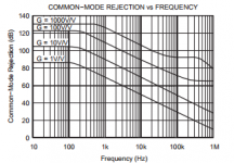
If CMRR is important for you, I have a bad news: increasing gain decreases CMRR.
The attached graph made me think different. Article here: https://e2e.ti.com/blogs_/b/analogwire/archive/2013/11/06/what-you-need-to-know-about-cmrr-instrumentation-amplifier-topologies-part-3
But I also have a good news: as long as resistors determine symmetry, you have to adjust only 1 of them! You can easily paralel as many INA as you want. I repeat: only as long as resistors determine gain. But in order to assure this, you need strong feedback, 40 dB at least, inside measurement bandwidth.
That sounds too good to be true actually...
Attachments
I didn't try other configurations, but in other threads I read about LNAs the common choice seems to be this one, because noise performance only gets worse the more stages you use.
If 1st stage amplifies 20 dB, then a similar second stage adds 1%. Who cares?
Of course I'd like to see a better design from you
I already given some advices to improve it.
The whole purpose of IC8 is to function as a buffer, together with adjacent parts like C45, to bootstrap R11 and R12 to better the common mode rejection. Adapted this from Whitlock, it's part of his InGenius patent. It's not supposed to be a 1028, but something cheap like an OP07.
Without C45 would CMRR be lower? I don't think so. The opposite.
Like it has been said, to better measure the performance of the regulator this thread is about.
Better? What was the previous measurement, and why was it not good enough?
Input impedance will thus be pretty low, so what's wrong about going low-value for feedback resistors? The discrete buffers might also help to take some load off the opamps so that they don't warm up as much and thus stay less noisy. If this all sounds unreasonable, I'd be probably better off buying an integrated INA, but where's the fun in that?
Discrete buffer is a source of problems, without any real reason.
Better? What was the previous measurement, and why was it not good enough?
My current preamp is a single opamp in non-inverting mode, set for 40dB gain followed by a buffer. With any length of cable connected to its input it collects lots of (presumably common mode) noise at mains frequency and its harmonics. I wrote about that about a month ago in this thread and thus came up with the design which started this discussion. My goal is now to a) build something with high CMRR to hopefully get rid off the mains noise (which is gone with the preamp running and the input left open [and thus no cable connected]) and b) to keep the noise as low as economically possible, which means no loads of expensive parts and no hard to get or special parts (like a transformer). But the more I think about it, it seems I've opened a much bigger can of worms than I expected - unfortunately I don't have the time I'd like to put in there at the moment, since there're more important things in life. So maybe it's best for me to be content with what I have at the moment, take all the precious information that all of you gave to me, and come back to this project at a later point in time.
or buy Frex's PCB.
Which one? That with 80dB gain and 500nV equivalent input noise?
At the moment I think it's actually the best for me to follow your advice and start out with a basic INA and see how it performs. If it helps eliminating the mains noise issues and thus performs better than my current amp, I'll keep it and be content. If it doesn't, I'll have a much more specific list of goals to achieve by then. Until yesterday I wanted to build an INA for high CMRR and try to keep its noise as low as possible, without even thinking about the input impedance. Those 47R are bad for noise performance, so I decided to leave them out. I got encouraged to use some low-value feedback resistors for lowest noise and use discrete buffers to drive them. I've come up with a pcb and then, all of a sudden, the whole concept is ill-conceived because all the gain in one stage is never a good solution. It severely limits bandwith. How much do I need? I'm fine with 20kHz, because that's the most I'll be looking at most of the time. 100kHz was mentioned instead. Lowering the gain and adding a second stage only adds 1% noise (I was told), so who cares? What's the point of a Low Noise Amplifier if I don't care about noise? Shouldn't I try to keep the overall noise as low as possible? Of course it all depends on the input impedance, but do I know beforehand how low a possible output impedance of a possible psu design might be? Sure, there might exist 'better' approaches with much lower noise, like transformers and paralleled, integrated and laser trimmed INAs, but that's not what I was after. It's always good to read other opinions and to reconsider one's approach from other perspectives, but discussing with several people and everyone has his own concept, saying this is bad and that is better, sometimes even contradicting each other with no proof from either side is rather tiring.
No offence, but this is pretty confusing for me. I read a patent about increasing CMRR, adopt it, and then Pafi says it's not going to work. More like the contrary. But no proof from his side. Now I am as far as I've been before, knowing not more and not less. Of course I could try this all for myself, but that's where the missing time comes in. I'm fine with trying and experimenting with one concept, but ending up with several concepts which have to be examined in the real world, and then have to be refined and/or combined afterwards, is way over my head right now.
If your Julia card has high input impedance that could be a harmonic noise pick up point too. I use an unbalanced to balanced (RCA --> XLR) Neutrik adapter plug for my EMU line in and that brings down a lot of pick up when driven from very low impedance. Because in SE its >1Meg when in balanced its 1.5k
I don't think it's the soundcard input. With the preamp connected via ~50cm standard quality RCA cord I don't get any mains noise spikes. Only with something connected to the preamp's input, be it a scope probe, RCA cord, double shielded coax; connected to anything, left open, shorted; I get the noise in the spectrum analysis. So it must be something picked up and amplified by the preamp. If it was due to the preamp itself, it must show with the preamp's input left open, but it doesn't.
- Status
- This old topic is closed. If you want to reopen this topic, contact a moderator using the "Report Post" button.
- Home
- Amplifiers
- Power Supplies
- The simplistic Salas low voltage shunt regulator