What do you know about ground loops?
Soundcard? It sounds to be a part of a PC, connected to PowerLine. It can be a source of many types of disturbances, both in voltage and current, depending on the details of grounding system.
Do you have a detailed report from your measurement? Link?
Soundcard? It sounds to be a part of a PC, connected to PowerLine. It can be a source of many types of disturbances, both in voltage and current, depending on the details of grounding system.
Do you have a detailed report from your measurement? Link?
This is basically it: LM317 regulator under test preamp.org
There's the schematic for the preamp, too.
There's the schematic for the preamp, too.
Okay, now I'm a little amazed  .
.
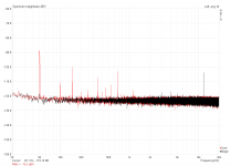
First image:
The red graph shows the preamp hooked up to a tracking dual adjustable supply built around LM317/337, with only the DC leading into the preamp's case. The spectrum looks like it did before, where I had the LM317/337 and rectifier inside the case and went in with the raw AC from a wall-wart transformer (no SMPS and no rectifier in there).
The black graph shows the preamp battery powered, with two 9V blocks lying on top of the case. All the noise is nicely gone.
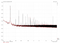
Second image:
Hooked up as before, one with battery and one with lab supply, but this time with a length of cable connected to the input. Well...

Edit: Preamp was set to 60dB
.First image:
The red graph shows the preamp hooked up to a tracking dual adjustable supply built around LM317/337, with only the DC leading into the preamp's case. The spectrum looks like it did before, where I had the LM317/337 and rectifier inside the case and went in with the raw AC from a wall-wart transformer (no SMPS and no rectifier in there).
The black graph shows the preamp battery powered, with two 9V blocks lying on top of the case. All the noise is nicely gone.
Second image:
Hooked up as before, one with battery and one with lab supply, but this time with a length of cable connected to the input. Well...
Edit: Preamp was set to 60dB
Attachments
Last edited:
This is basically it: LM317 regulator under test preamp.org
There's the schematic for the preamp, too.
Thanks!
It's well documented! Congrats!
I'll be back!
Okay, now I'm a little amazed
...
First image:...
The first part is more or less clear, however it doesn't seem to be really similar to your earlyer noise floor measurement: http://preamp.org/lm317/000/fft_000.png the numbers are quite different. But I guess this is because you didn't short input now, but did it earlyer. Or you scaled 60 dB down before, but now you left it unchanged. Correct me if Im wrong. And always tell these status when share measurement result.
I will draw an explanation soon. There is a simple solution also, requiring 1 extra piece of wire and a ferrite ring.
The second part is a little unclear, but I have a guess. What kind of wire you connected? Shielded or not? Did you connect the end to a low impedance (or shorted)? The relevant test should be made with shielded cable, and connected input to shield directly or through a low impedance (just like during measurement). I bet it was not the case, you must have used an unshielded cable, or shielded but didn't connect the end, or both problems.
ground loop problem + solution
Preamp,
I don't have all neccessary data in my hands, but the situation seems to be something like this:

The capacitive disturbance flows through GND wires and a voltage drops. This is partly directly act as a signal, partly can be amplified by preamp if GND layout is not careful enough (R6=track resistance). I have no data to tell which one is dominant in your setup but I suspect the second to be bigger.
How to solve? The first solution, wich works almost always is to provide a bypass for ground current, and increase signal GND impedance. Like this:

But some GND current will still be there, so you can further decrease disturbance by avoiding internal GND loop inside preamp (if there is).

Actually this is just the beginning, far from the final solution, because DUT is still nowhere. It also injects a noise current that must be bypassed, and this flows through quite a big resistance (shield of the measurement cable) and amplified by 60 dB, so it's even more important to deal with. Picture comes later...
Preamp,
I don't have all neccessary data in my hands, but the situation seems to be something like this:
The capacitive disturbance flows through GND wires and a voltage drops. This is partly directly act as a signal, partly can be amplified by preamp if GND layout is not careful enough (R6=track resistance). I have no data to tell which one is dominant in your setup but I suspect the second to be bigger.
How to solve? The first solution, wich works almost always is to provide a bypass for ground current, and increase signal GND impedance. Like this:
But some GND current will still be there, so you can further decrease disturbance by avoiding internal GND loop inside preamp (if there is).
Actually this is just the beginning, far from the final solution, because DUT is still nowhere. It also injects a noise current that must be bypassed, and this flows through quite a big resistance (shield of the measurement cable) and amplified by 60 dB, so it's even more important to deal with. Picture comes later...
Last edited:
ground loop problem + DUT + solution
So with the Device Under Test, the situation is getting worse because noise voltage drops on measurement cable as I mentioned:

No problem, we already known the trick, shunt the current! (Unfortunately we can't shunt 2 currents independently, so at this point we must use batteries to supply the preamp.) Be careful, connect the extra wire to a point as close to the GND (reference potential) of DUT as you can!

Still not perfect, because some current is left. Now we can move to balanced signalling. Actually for this we don't need any special circuit, just use what we already have, + an extra signal (reference potential, to be exactly) wire, also shielded together with the signal line. Well, R10 is actually not really neccessary...

If you did this all, and understood as well, and everything works perfectly, then you can step back a little bit, and may use the transformer again, to save batteries, since now the output is barely affected by the GND currents. What is more, you can also remove common mode filters and GND shunt. This way some disturbance comes back, but it must be tolerable.
.GIF")
But please, don't jump to the end immediately, since I've made many assumptions, and if something is significantly different in your test bed, then the complete solution may not work as intended.
I know only 1 thing for sure: you don't need to build such a complicated circuit for this particular task. And maybe if you build it, the problem can still remain if you don't analyse it and don't solve it. Basically you have a single ended signal to measure. No need for high CMR.
Read, analyse the schematics, and if you understood, then you can do whatever you want.
So with the Device Under Test, the situation is getting worse because noise voltage drops on measurement cable as I mentioned:
No problem, we already known the trick, shunt the current! (Unfortunately we can't shunt 2 currents independently, so at this point we must use batteries to supply the preamp.) Be careful, connect the extra wire to a point as close to the GND (reference potential) of DUT as you can!
Still not perfect, because some current is left. Now we can move to balanced signalling. Actually for this we don't need any special circuit, just use what we already have, + an extra signal (reference potential, to be exactly) wire, also shielded together with the signal line. Well, R10 is actually not really neccessary...
If you did this all, and understood as well, and everything works perfectly, then you can step back a little bit, and may use the transformer again, to save batteries, since now the output is barely affected by the GND currents. What is more, you can also remove common mode filters and GND shunt. This way some disturbance comes back, but it must be tolerable.
But please, don't jump to the end immediately, since I've made many assumptions, and if something is significantly different in your test bed, then the complete solution may not work as intended.
I know only 1 thing for sure: you don't need to build such a complicated circuit for this particular task. And maybe if you build it, the problem can still remain if you don't analyse it and don't solve it. Basically you have a single ended signal to measure. No need for high CMR.
Read, analyse the schematics, and if you understood, then you can do whatever you want.
Last edited:
Or you scaled 60 dB down before, but now you left it unchanged. Correct me if Im wrong. And always tell these status when share measurement result.
Correct. Input was shorted, too. Will do.
What kind of wire you connected? Shielded or not? Did you connect the end to a low impedance (or shorted)? The relevant test should be made with shielded cable, and connected input to shield directly or through a low impedance (just like during measurement). I bet it was not the case, you must have used an unshielded cable, or shielded but didn't connect the end, or both problems.
The cable I used is a RG-59 type with extra foil layer and a BNC connector on one end. The other end is connected via screw clamps to the output of my latest Dual Salas prototype, which was just lying there in the open, not connected to anything else.
I will draw an explanation soon. There is a simple solution also, requiring 1 extra piece of wire and a ferrite ring.
Thank you for this thorough explanation! I will definitely go through all this and gain experience along the way. It might take me some days, but I'll get back here with the results.
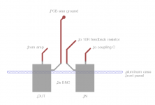
Just to sort out some possible issues with my preamp build, I've attached a sketch of how I placed the connectors. I use 2 non-insulated BNC connectors, placed physically close together, and in direct electrical contact with the aluminum front panel. Each connector has a solderable contact fin beneath the washer, of which one is connected to the star ground on the pcb and the other one to the feedback resistor. This connection is the first change I just tried, as before both fins and the feedback resistor were each individually connected to the star ground point. Looking at the spectrum now didn't show any difference though. Question: would it be better to have the connectors insulated from the front panel to avoid grounding problems?
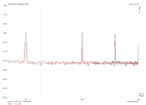
Other thing I tried was to connect the double-shielded coax to the input and directly short the ends. This is the red trace. Lab supply was used. The black trace shows the input shorted with a BNC plug (which originally contained a 50R resistor that I replaced with a wire link). Any idea why the "short cable" looks worse than half a metre of shielded coax (which looks even worse if it is connected to a DUT)?
Other thing I tried was to connect the double-shielded coax to the input and directly short the ends. This is the red trace. Lab supply was used. The black trace shows the input shorted with a BNC plug (which originally contained a 50R resistor that I replaced with a wire link). Any idea why the "short cable" looks worse than half a metre of shielded coax (which looks even worse if it is connected to a DUT)?
Attachments
the BNC is an unbalanced connector.
It uses the screen as both signal return and as the grounding side of the interchassis coupling.
If one needs to avoid contaminating very small signals, then the screen MUST have it's two functions separated.
The screen is an interchassis coupling.
The screen connects chassis to chassis.
Use a balanced impedance connection to separate the signal return from the chassis coupling screen.
Use a balanced impedance connection to separate the signal return from the chassis coupling screen.
Any suggestions for a decent connector or cable? The obvious way would be to use XLR - two wires and a screen...
Guess I'll have to find it out myself, but what about shield coverage? Is 100% (i.e. foil) a necessity or will 85% be alright?
What about the attached connectors? They're cheap to get, all-metal and completely shielded, lots of connectors (4 to 8 plus shield) and screw-in for a permanent connection.
Using two BNC connectors with two coax cords for signal and ground ref seems a bit cumbersome, but should be OK noise-wise, right? The screen would be connected at the BNC side only and terminate just before where the inner conductors are connected to the DUT.
Attachments
Indeed, XLR is the preferred connector family for balanced lines at these frequencies. Minimize loop area! The star quad cable is better than shielded twisted pair. Ideally the shield coverage should be very good. If it is not going to flex a lot a foil shield under a braid shield is good. Double braid shields are fairly good for things that flex a lot.Any suggestions for a decent connector or cable? The obvious way would be to use XLR - two wires and a screen...
Guess I'll have to find it out myself, but what about shield coverage? Is 100% (i.e. foil) a necessity or will 85% be alright?
What about the attached connectors? They're cheap to get, all-metal and completely shielded, lots of connectors (4 to 8 plus shield) and screw-in for a permanent connection.
Using two BNC connectors with two coax cords for signal and ground ref seems a bit cumbersome, but should be OK noise-wise, right? The screen would be connected at the BNC side only and terminate just before where the inner conductors are connected to the DUT.
I need to get more of both the wire and the connectors! I had a breadboard that needed a true balanced generator feed and wound up sacrificing some mic cable, and departed from the XLR connection at the AP using a dual banana plug along with a single plug for the system common. The difference in the DUT output noise was easy to see compared to a single coax feed, even though I had a U attenuator right at the DUT (~ -20dB, constructed to have a balanced R of 200 ohms when driven from the 50 ohm AP balanced generator output).
Just to sort out some possible issues with my preamp build, I've attached a sketch of how I placed the connectors. I use 2 non-insulated BNC connectors, placed physically close together, and in direct electrical contact with the aluminum front panel. Each connector has a solderable contact fin beneath the washer, of which one is connected to the star ground on the pcb and the other one to the feedback resistor. This connection is the first change I just tried, as before both fins and the feedback resistor were each individually connected to the star ground point. Looking at the spectrum now didn't show any difference though. Question: would it be better to have the connectors insulated from the front panel to avoid grounding problems?
Its not easy to tell. Grounding must be designed together with signal path, including active parts. As you can see in my simulations once I changed GND, the other time the signal path. You can't design them separately in a single ended system, since it was a ground loop. (OK, actually a ground loop is permitted if there is only insignificant current, and there is no flux changing inside.)
I think a photo could tell me more.
Other thing I tried was to connect the double-shielded coax to the input and directly short the ends. This is the red trace. Lab supply was used. The black trace shows the input shorted with a BNC plug (which originally contained a 50R resistor that I replaced with a wire link). Any idea why the "short cable" looks worse than half a metre of shielded coax (which looks even worse if it is connected to a DUT)?
I don't know yet. Maybe its just a coincidence, a different factor changed. Maybe contact resistance is too high. Too many possible reasons. To make it sure I suggest you to amplify the signal and connect to a speaker, this way you can hear everything as soon as you modify. You can touch the box and you will hear the hum. Etc...
The fastest spectrum analyser is inside your head.
Here's a photo. The layout is a little different from the schematic (layout was for an inverting amp), so I had to make some changes. The two vertical resistors between the switches are both 10R; the one with the brown wire is 'the one', the other one can be switched in parallel for another 6dB gain. The rightmost switch is not used anymore and the tracks are cut so they don't radiate or receive anything. Same thing for the psu around the LM317/337, only running three wires directly to the caps, the tracks to the regulators are cut.
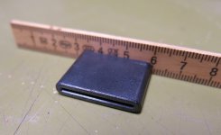
What about the ferrite? This is the only thing I could find lying around here.
Once it becomes a common mode choke, should I simply place it between the output BNC connector and its pcb connector? The ground shunt wire will run to the star ground point, right?
What about the ferrite? This is the only thing I could find lying around here.
Once it becomes a common mode choke, should I simply place it between the output BNC connector and its pcb connector? The ground shunt wire will run to the star ground point, right?
Attachments
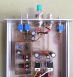
Need to see ground and signal tracks. How you connected internal shielding? What about metal parts of 2 switches? Should be grounded! Right one also, despite you don't use it. (Not serious problem, but still...)
I'm not sure about your case connections. Anodised aluminium can insulate. Connectors must have a low resistance connection, and every sides must have a fair connection to act as a faraday box.
No. You have to place it on the signal cable. You need a bigger ferrite.
But first let's clean the internal GND mess!
I'm not sure about your case connections. Anodised aluminium can insulate. Connectors must have a low resistance connection, and every sides must have a fair connection to act as a faraday box.
should I simply place it between the output BNC connector and its pcb connector?
No. You have to place it on the signal cable. You need a bigger ferrite.
But first let's clean the internal GND mess!
Need to see ground and signal tracks.
You can basically see them shining through the pcb. The right BNC (output) ground runs straight to the star ground and is the only connection for the metal case. The switches have a separate track to the star ground. The small metal box has a circumferential track beneath, which is connected with a track to the star ground. I have placed guard tracks around the signal tracks where it was possible.
Should I run the coax cable to the DUT a few times through a ferrite as a whole?
Guys! I know balanced signalling is the best, but
- I don't think it is really neccessary in this particular case.
- With proper grounding, balanced system can be perfect. Without it, just much better then unbalanced system. And the DUT is unbalanced, just like the final audio system. So making GND things right is beneficial. So lets do it first! In a balanced system GND problems may covered by CMR, so you can't debug then.
A screen with low resistance is recommended. H.Ott tells us to never use a screen that has a drain wire.Any suggestions for a decent connector or cable? The obvious way would be to use XLR - two wires and a screen...
Guess I'll have to find it out myself, but what about shield coverage? Is 100% (i.e. foil) a necessity or will 85% be alright?
What about the attached connectors? They're cheap to get, all-metal and completely shielded, lots of connectors (4 to 8 plus shield) and screw-in for a permanent connection.
Using two BNC connectors with two coax cords for signal and ground ref seems a bit cumbersome, but should be OK noise-wise, right? The screen would be connected at the BNC side only and terminate just before where the inner conductors are connected to the DUT.
If you can afford a double braided screen and a foil screen, then you get the foil giving 100% for the HF and the double braiding giving low resistance and 95% coverage for the lower F.
Do not leave long exposed cores outside the screen at the terminations.
And DO NOT us long pigtails to terminate the screen.
Absolutely NOT !!!!Using two BNC connectors with two coax cords for signal and ground ref seems a bit cumbersome, but should be OK noise-wise, right?
Last edited:
- Status
- This old topic is closed. If you want to reopen this topic, contact a moderator using the "Report Post" button.
- Home
- Amplifiers
- Power Supplies
- The simplistic Salas low voltage shunt regulator