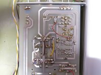
I see a bunch of tracks, but can not identify which one is which node.
Does this help? I'd have shown you the layout from EAGLE, but since it's modified a lot I thought it would be rather more difficult to 'read'.
And DO NOT us long pigtails to terminate the screen.
If the screen is solely for screening, I'd rather flip it back and tape it down with some copper tape, just like it is recommended for Cat.6a Keystone Modules. Else If the screen is used as the second conductor, which is what I'm doing now but probably should stop doing, then it's the easiest thing to do...
Absolutely NOT !!!!
Why? This way I'd have two signal conductors which are shielded separately and could use some double-braid plus foil Satellite type coax cable, which I have plenty of.
Attachments
I cant match different pictures with mobile phone, so now its not enough to reconstruct the signal pathes.
Back to basics. Do you understand the first schematic?
First step that you must do even if you rebuild preamp to balanced: If you want to know if output cable is good enough, you can make an experiment. Use only this cable, terminate its input, and connect a "current injector" to the shield near its input! A current injector is any secondary pin of a transformer, primer is plugged in. Measure noise!
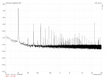
...with lab supply, but this time with a length of cable connected to the input. ... Input was shorted, too.
-70 dB
Other thing I tried was to connect the double-shielded coax to the input and directly short the ends. This is the red trace. Lab supply was used.
-100 dB
What did you do differently???
Frustrating (the way you tell only little pieces of the story).
I cant match different pictures with mobile phone, so now its not enough to reconstruct the signal pathes.
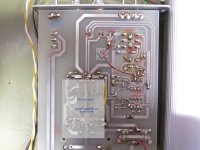
And I ain't got X-ray... Added some notations that will hopefully make it somewhat easier.
Back to basics. Do you understand the first schematic?
If that means to wrap the preamp's output cable through a ferrite ten times and directly connect that output's cable shield far end (that would connect to the soundcard in my case) with the power supply ground point via a separate wire, then yes. Else, probably not.

And your schematic is not up-to-date.
Why not? Didn't see anything wrong.
R8 is connected to noisy GND (-> GND star, in case you supply it by external PSU). Do you use it?
No, I don't use R8. Ignore it please, as to not make matters worse here.
-70 dB
-100 dB
What did you do differently???
Like I told in post #7290, I removed the ground connection of R3 from the star ground and directly connected it to the input BNC connector. I drew that up in the sketch in the same post. So the first value comes from R3 connected to the noisy star ground and with the measurement cable connected to the unpowered DUT. I also tried to short the wire at the DUT but didn't show a trace of that, because it looked basically the same. Now that I think about it, it was probably due to the DUT still being connected, albeit the cable was shorted. And the second value comes from the shorted measurement cable, not connected to the DUT, and R3 directly connected to the input BNC connector.
Attachments
It was not clear when did you change it. Especially because you said
So... we have a result of 30 dB improvement, but dont know why, since not tested in the same environment. You can attach DUT the same way as before, and measure the result. Based on the result I will be able to advise the next step.
But you also can do the output cable test as written before.
There are many ways to figure out how big disturbance is caused by each components. Basically you have 3 stages and 3 current injectors. The stages are: 1: input cable, 2: preamp, 3: output cable. The current injectors are transfer capacitance of transformers A: in DUT, B: in PSU of preamp, and C: stray capacitance of environment (this is unfortunately a distributed network, varaiable, but smaller). There are 9 combinations, for each there is a specific disturbance level. What you measure, is the sum of them. You can measure them, and then you can eliminate them as much as you tolerate and as much as you take the effort. Probably you eliminated A2, B2 and C2 already (by changing connection of R3), but didn't test, because in the earlyer test there was a much higher C1, so you can compare them.
which is contradictional, since there were no similar spectum within the published results. Or difference between what?Looking at the spectrum now didn't show any difference though.
So... we have a result of 30 dB improvement, but dont know why, since not tested in the same environment. You can attach DUT the same way as before, and measure the result. Based on the result I will be able to advise the next step.
But you also can do the output cable test as written before.
There are many ways to figure out how big disturbance is caused by each components. Basically you have 3 stages and 3 current injectors. The stages are: 1: input cable, 2: preamp, 3: output cable. The current injectors are transfer capacitance of transformers A: in DUT, B: in PSU of preamp, and C: stray capacitance of environment (this is unfortunately a distributed network, varaiable, but smaller). There are 9 combinations, for each there is a specific disturbance level. What you measure, is the sum of them. You can measure them, and then you can eliminate them as much as you tolerate and as much as you take the effort. Probably you eliminated A2, B2 and C2 already (by changing connection of R3), but didn't test, because in the earlyer test there was a much higher C1, so you can compare them.
Last edited:
So... we have a result of 30 dB improvement, but dont know why, since not tested in the same environment. You can attach DUT the same way as before, and measure the result. Based on the result I will be able to advise the next step.
Re-ran the measurement with the DUT connected as before. Looks pretty much the same to me, so the DUT must be a pretty good antenna for EMI and stuff.
But you also can do the output cable test as written before.
Results here.
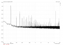
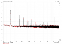
Gray trace: Output cable connected to soundcard, input left open
Black trace: input shorted. Note 50Hz is gone.
Red trace: input shorted and shield connected to transformer secondary
The spikes above 50Hz are most probably due to the computer's psu, as they were slowly but constantly moving upwards in frequency. I had powered it up just prior to the measurements, so you can tell in which order I proceeded.
The spectrum with the DUT connected shows lots of even order harmonics way up into the kHz, while they're basically absent with the soundcard only. They're probably swamped by the noise floor.
Attachments
hi everyone,
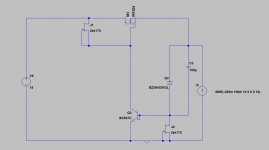
i wanted to experiment with other regulators for my digital gear as i found out they benefited from low output impedance (it seems) and Salas shunts are designed for analog stages.
i tried a tl431 controling a bjt in series (kind of cap multipier configuration) and it did not sound as bad as i thought it might.
so then i thought about a "series Salas reg" that would give more headroom for active devices to perform
you guys think it s worth playing with?
Attachments
Re-ran the measurement with the DUT connected as before. Looks pretty much the same to me, so the DUT must be a pretty good antenna for EMI and stuff.
Sorry, I was wrong, not the same way! You should connect DUT only to the input GND of preamp, while input is shorted, this way you can avoid activating C1 coupling. But unfortunately there is no this type of measurement was made before modification. :-(
Results here.
Gray trace: Output cable connected to soundcard, input left open
Black trace: input shorted. Note 50Hz is gone.
Red trace: input shorted and shield connected to transformer secondary
OK, it's not so bad. You will be able to improve it with the common mode filter.
The spikes above 50Hz are most probably due to the computer's psu, as they were slowly but constantly moving upwards in frequency. I had powered it up just prior to the measurements, so you can tell in which order I proceeded.
The spectrum with the DUT connected shows lots of even order harmonics way up into the kHz, while they're basically absent with the soundcard only. They're probably swamped by the noise floor.
Can you show the waveform (filtered)? Maybe somehow the rectified voltage affected the system.
Next:
The biggest improvement can be made by bypassing input cable. The best would be a shielded, balanced cable, but you will also need an appropriate connector with 2 poles at least + shield. I don't recommend any specific, pick one that fits there! Or solder it directly inside the box!
hi everyone,
i wanted to experiment with other regulators for my digital gear as i found out they benefited from low output impedance (it seems) and Salas shunts are designed for analog stages.
i tried a tl431 controling a bjt in series (kind of cap multipier configuration) and it did not sound as bad as i thought it might.
so then i thought about a "series Salas reg" that would give more headroom for active devices to perform
you guys think it s worth playing with?
Turning it around as series topologically looks ok in your schematic but I would worry about stability issues in practice. Better breadboard it to test it does not oscillate.
You should connect DUT only to the input GND of preamp, while input is shorted, this way you can avoid activating C1 coupling.
To avoid any further mistakes. My measurement cable (shielded coax) is connected to the DUT via screw clamps, shield to ground and central conductor to positive output of DUT. The other end of the measurement cable (fitted with a BNC connector) is connected to the preamp's input. Where should I short the input now, at the DUT or inside the preamp? I'll take a measurement then, undo the modification (gnd point of R3) and take another measurement for reference.
Can you show the waveform (filtered)? Maybe somehow the rectified voltage affected the system.
ARTA doesn't filter the waveform prior to display, only the spectrum. I can offer you to attach the unfiltered data as ASCII files like this:
Code:
Time Record
NumSamples = 8192
SamplingRate = 48000 Hz
FullScale = 3.161300 V
Left(V)          Right(V)
9.835950E-005	-7.537126E-007
-6.029701E-005	-3.768563E-006
-2.483483E-004	-8.667696E-006
-1.790067E-004	4.522276E-006
6.067387E-005	-6.783414E-006
2.336509E-005	-1.507425E-006
3.542449E-005	7.537126E-006
-1.808910E-005	1.507425E-006
-7.235642E-005	4.522276E-006
1.869207E-004	-8.667696E-006
(...)	(...)
Maybe you can use that with some more elaborate software and apply filtering for yourself? And which one do you want to see, that with the DUT or the cable? Open, shorted, injected?
I will try a balanced cable, but I have to order some first. Two coax' would be no problem, but according to Andrew this is not going to work.
shield to Chassis.shield to ground
according to a very old Thread this does not work. Might have been J.Neutron that contributed.I will try a balanced cable, but I have to order some first. Two coax' would be no problem, but according to Andrew this is not going to work.
jneutron has contributed to two very long threads and 18 others that mentions shield.
Last edited:
shield to Chassis.
DUT does not have a chassis yet.
To avoid any further mistakes. My measurement cable (shielded coax) is connected to the DUT via screw clamps, shield to ground and central conductor to positive output of DUT. The other end of the measurement cable (fitted with a BNC connector) is connected to the preamp's input. Where should I short the input now, at the DUT or inside the preamp? I'll take a measurement then, undo the modification (gnd point of R3) and take another measurement for reference.
Disconnect central conductor at DUT, and short it inside preamp!
ARTA doesn't filter the waveform prior to display, only the spectrum. I can offer you to attach the unfiltered data as ASCII files like this:
Code:Time Record NumSamples = 8192 SamplingRate = 48000 Hz FullScale = 3.161300 V Left(V) Right(V) 9.835950E-005 -7.537126E-007 -6.029701E-005 -3.768563E-006 -2.483483E-004 -8.667696E-006 -1.790067E-004 4.522276E-006 6.067387E-005 -6.783414E-006 2.336509E-005 -1.507425E-006 3.542449E-005 7.537126E-006 -1.808910E-005 1.507425E-006 -7.235642E-005 4.522276E-006 1.869207E-004 -8.667696E-006 (...) (...)
Maybe you can use that with some more elaborate software and apply filtering for yourself? And which one do you want to see, that with the DUT or the cable? Open, shorted, injected?
OK, for curiosity I'll try to take time for processing. All of them can be interesting, but the one with DUT may show something special.
I will try a balanced cable, but I have to order some first. Two coax' would be no problem, but according to Andrew this is not going to work.
Two coax solution is suboptimal, but better than the current state. You need to connect shields together at both ends, and align them tightly together.
But on the other end what about your PC? Is it earthed correctly? (How?)
Disconnect central conductor at DUT, and short it inside preamp!
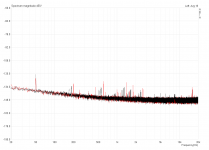
Why would I do that for practical purpose? Just did it for a test (with R3 connected to the BNC connector), the spectrum shows virtually no difference. The red trace is with the input shorted inside and the BNC connector left open, the black trace is with the coax connected, DUT hooked up to the shield and central connector left open at the DUT.
OK, for curiosity I'll try to take time for processing
You only need the left channel. I've attached two runs with the DUT connected like before (signal and shield connected), one with R3 connected to the star ground (dut_org) and one with R3 connected to the BNC connector (dut_mod).
But on the other end what about your PC? Is it earthed correctly? (How?)
It is connected to PE via its psu and a standard three-prong "Schutzkontakt-Stecker". The preamp and DUT are not earthed. The lab supply I'm currently using is earthed like the PC via SCHUKO, but the wall wart I used before was not, and it didn't make much of a difference, if at all.
I'll try to find a biscuit tin (gave them all to my mom lately so that she can refill them
) and put the DUT in there. As long as I do not have a differential cable, how would I connect it? With a separate ground wire directly to the case of the preamp?Attachments

The lab supply I'm currently using is earthed like the PC via SCHUKO
Is there any galvanic connection between secondary (GND) and protective earth?
Is there any galvanic connection between secondary (GND) and protective earth?
No, it is not. Just checked it with a multimeter to be sure.
I have put the DUT into a biscuit tin and connected that tin to the preamp's case with a separate wire. Of course the faraday cage was not 100% sealed, but the spectrum changed visibly. 50Hz dropped considerably from ~-67dB to ~-100dB, 100Hz went up by roughly 10dB and 150Hz again went some 10dB down. Looks somewhat better, but still too noisy for what I want.
Attachments
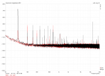
Why would I do that for practical purpose?
To test immunity of preamp for current injection without disturbances picked up by input cable.
Just did it for a test (with R3 connected to the BNC connector), the spectrum shows virtually no difference.
The red trace is with the input shorted inside and the BNC connector left open,
While the input cable was... ? And DUT was... ?
the black trace is with the coax connected, DUT hooked up to the shield and central connector left open at the DUT.
What about central connector in the preamp?
Try to understand the things I explained with simulated schematic! You can ask. But I'm too tired to investigate what you did.
It is connected to PE via its psu and a standard three-prong "Schutzkontakt-Stecker". The preamp and DUT are not earthed. The lab supply I'm currently using is earthed like the PC via SCHUKO, but the wall wart I used before was not, and it didn't make much of a difference, if at all.
You test a complete system. 1 strong disturbance source can hide many other saller ones. If lab supply is earthed on it's output GND, then this is a strong ground loop.
I'll try to find a biscuit tin (gave them all to my mom lately so that she can refill them
Don't bother make a case for preamp (yet). There are no sensitive parts, except input cable, but you can't eliminate this with a case.
- Status
- This old topic is closed. If you want to reopen this topic, contact a moderator using the "Report Post" button.
- Home
- Amplifiers
- Power Supplies
- The simplistic Salas low voltage shunt regulator